
Method and apparatus for applying thermal energy to tissue asymmetrically

a technology of thermal energy and tissue, applied in the field of percutaneous surgery, can solve the problems of not having the capability of delivering heat to only one side of the tip, adverse effects on otherwise healthy tissue, and electrode tips of the prior art not being designed

Inactive Publication Date: 2001-01-23
ORATEC INTERVENTIONS
View PDF180 Cites 485 Cited by
  • Summary
  • Abstract
  • Description
  • Claims
  • Application Information

AI Technical Summary

Problems solved by technology

However, a limitation of this technology has been that tissue that is to be treated by exposure to thermal energy is often close to tissue that should not be exposed to the thermal energy, resulting in potentially adverse affect to otherwise healthy tissue.
However, the lesion would be surrounded by other very sensitive tissues that should not be treated.
The electrode tips of the prior art do not have the capability of delivering heat to only one side of the tip.
The electrode tips of the prior art have not been designed in a way that would allow the surgeon to place the electrode tip in between two layers of tissue and only provide the therapy to one of those two layers (i.e., to one side of the electrode tip).
As a result of these limitations, the prior art tips run a risk of causing injury and necrosis to sensitive tissue.
Heating and death of sensitive tissue (e.g., a spinal nerve root) can lead to loss of sensation and mechanical control of various parts of the body (e.g., the foot) or, as another example, loss of bowel control.
In the brain the effects being risked could be very devastating.

Method used


Image

  • Method and apparatus for applying thermal energy to tissue asymmetrically
  • Method and apparatus for applying thermal energy to tissue asymmetrically
  • Method and apparatus for applying thermal energy to tissue asymmetrically

Examples


Embodiment Construction

The present invention and the various features and advantageous details thereof are explained more fully with reference to the nonlimiting embodiments that are illustrated in the accompanying drawings and detailed in the following description. Descriptions of well known components and processing techniques are omitted so as not to unnecessarily obscure the present invention in detail.

This invention applies to the area of applying thermal energy to tissue during surgery in many different aspects of the body. The invention is especially applicable in those areas of the body where there are specific sensitivities in the surgery being performed such that the prior art does not allow for adequate addressing of the therapeutic need while providing the needed safety element in those certain areas. The reason for that is due to the proximity of tissue which should not be heated next to tissue that is intended to be treated and heated.

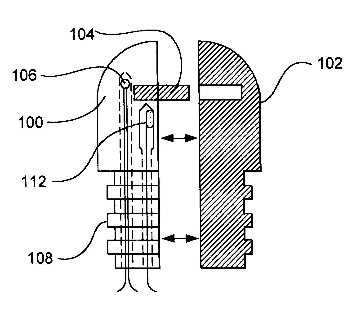
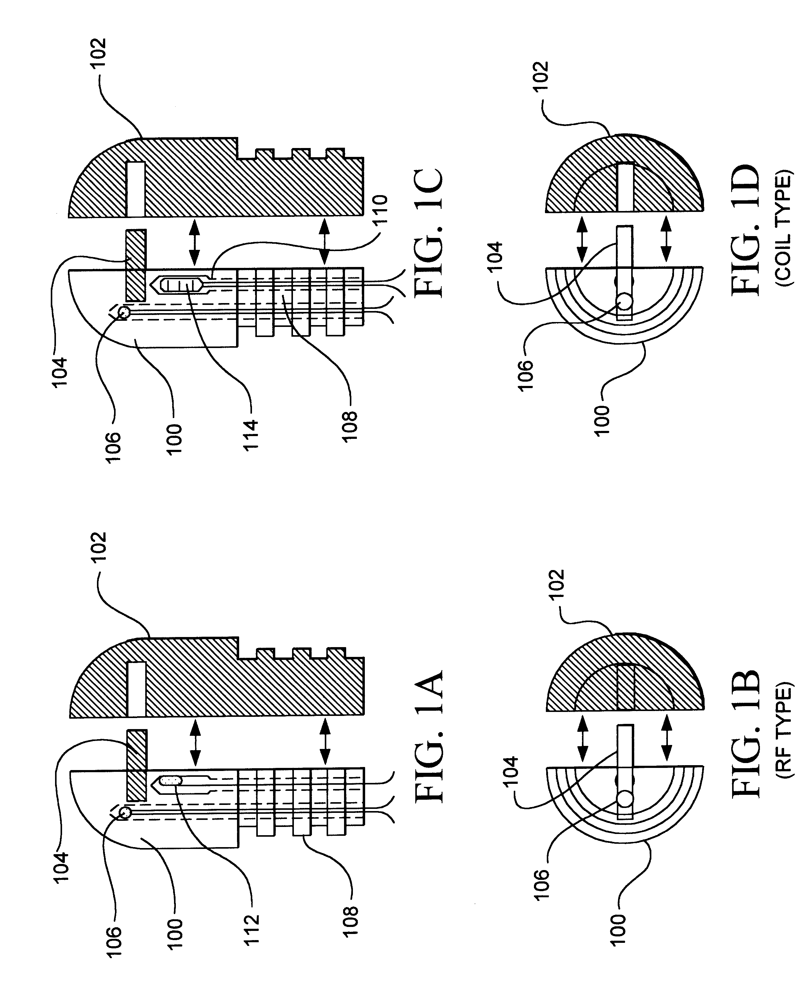
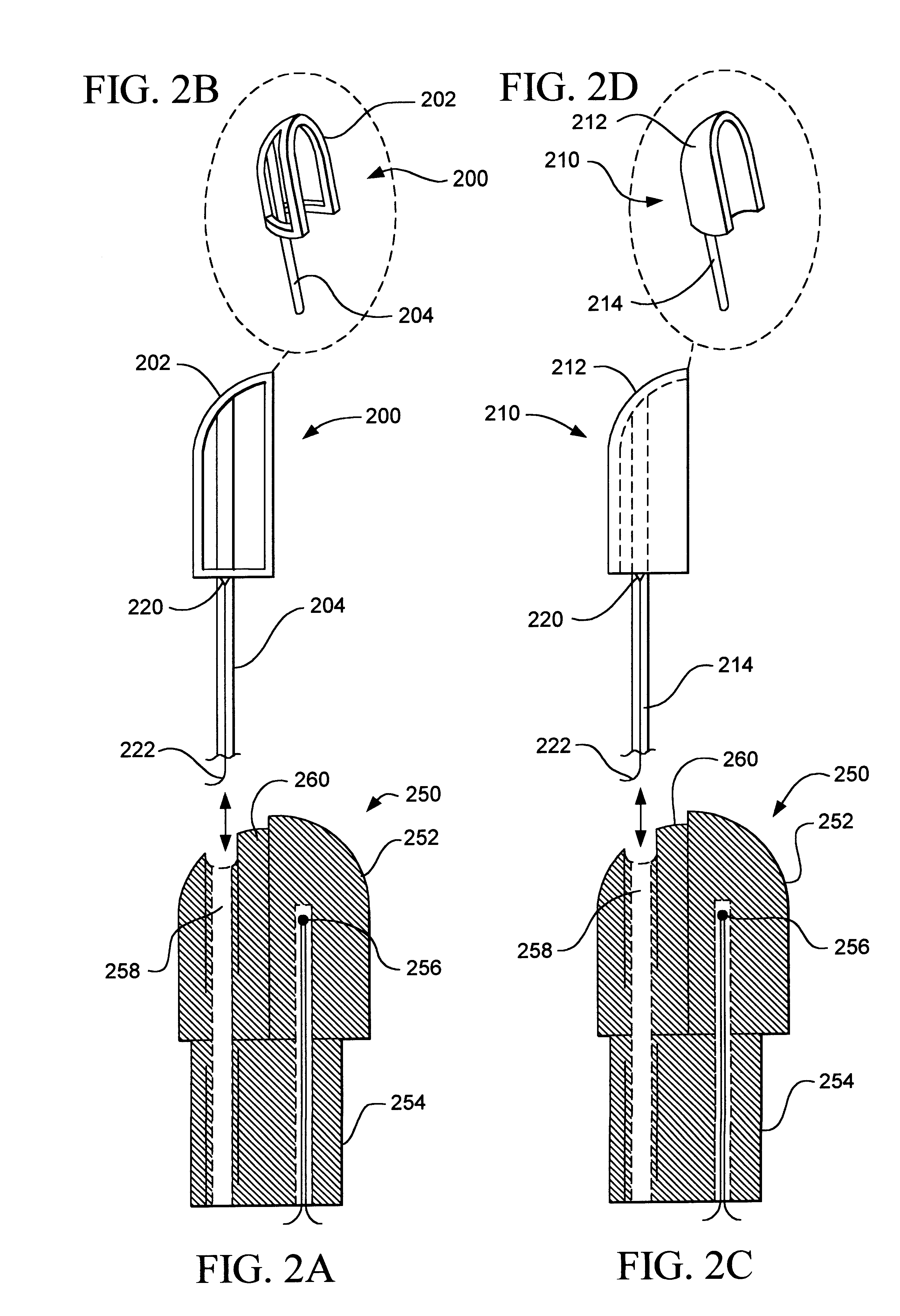
FIGS. 1A-D and FIG. 2 show detailed views of alternate em...


PUM


Abstract

Systems and methods are described for treating tissue with thermal energy while minimizing the amount of thermal energy to which adjacent tissue is exposed. A surgical instrument for delivering thermal energy to a section of tissue during percutaneous surgery, includes: an elongated shaft having a proximal end and a distal end; and a split tip electrode coupled to the distal end, the split tip electrode i) including a first component and a second component coupled to the first component, and ii) defining a principle axis. The thermal energy is delivered to the section of tissue so as to heat the section of tissue asymmetrically with regard to the principle axis of the split tip electrode. The systems and methods provide advantages in that thermal energy can be directed to one side of the split tip so that a first of two juxtaposed areas of a surgical site can be heated while a second of the two juxtaposed layers is substantially not heated. In alternate embodiments a portion of the site may be actively cooled while an adjacent portion of the site may be actively cooled.

Description

1. Field of the InventionThe present invention relates generally to the field of surgery. More particularly, the present invention relates to methods and apparatus for applying thermal energy to tissue during percutaneous surgery. Specifically, a preferred implementation of the present invention relates to an elongated catheter with a longitudinally split tip for directing thermal energy toward one side of the catheter during percutaneous surgery. The present invention thus relates to a surgical method and apparatus of the type that can be termed split tip.2. Discussion of the Related ArtThere has been previous medical experience with the use of surgical apparatus for delivery of thermal energy to tissue during percutaneous intervention. Prior art apparatus for applying thermal energy to tissue, sometimes called electrode tips, have been powered by radio frequency (RF) generators. For example, see U.S. Pat. Nos. 5,458,596; 5,514,130; and 5,569,242, the entire contents of which are h...

Claims


Application Information

Patent Timeline
Patent Type & Authority Patents(United States)
IPC IPC(8): A61B18/04A61B18/08A61B18/14A61B18/00
CPCA61B18/08A61B18/1482A61B2018/00023A61B2018/00029A61B2018/00047A61B2018/00821
Inventor ASHLEY, JOHN E.
Owner ORATEC INTERVENTIONS
Learn More