Optical network loss-of-signal detection

a technology of optical network and loss of signal, applied in the field of optical network loss of signal detection, can solve the problems of channel power being an unreliable indicator, signal loss may be detected, use of such dither or other forms of tracing signatures may not be acceptable in a highly complex network accessed by many users

Inactive Publication Date: 2001-01-23
CIENA
View PDF15 Cites 84 Cited by
  • Summary
  • Abstract
  • Description
  • Claims
  • Application Information

AI Technical Summary

Problems solved by technology

Channel power is however an unreliable indicator of signal presence because, in the absence of a data carrying signal, optical amplifiers and repeaters in a span of the network will tend to compensate by amplifying random noise, thereby fully or partially restoring the level of optical channel power in the absence of the data carrying signal.
It is alternatively proposed that loss of signal may be detected as a result of the decoding process since the decoding apparatus will be unable to maintain synchronisation with a frame structure of received signals when a loss of signal condition exists.
The use of such dither or other forms of tracing signatures however may not be acceptable in a highly complex network accessed by many users and it would be preferable to avoid the need to modify the content of the optical signals carried by the system.

Method used


Image

  • Optical network loss-of-signal detection
  • Optical network loss-of-signal detection
  • Optical network loss-of-signal detection

Examples


second embodiment

A second embodiment will now be described with reference to FIG. 10 using corresponding reference numerals to those of preceding figures where appropriate for corresponding elements.

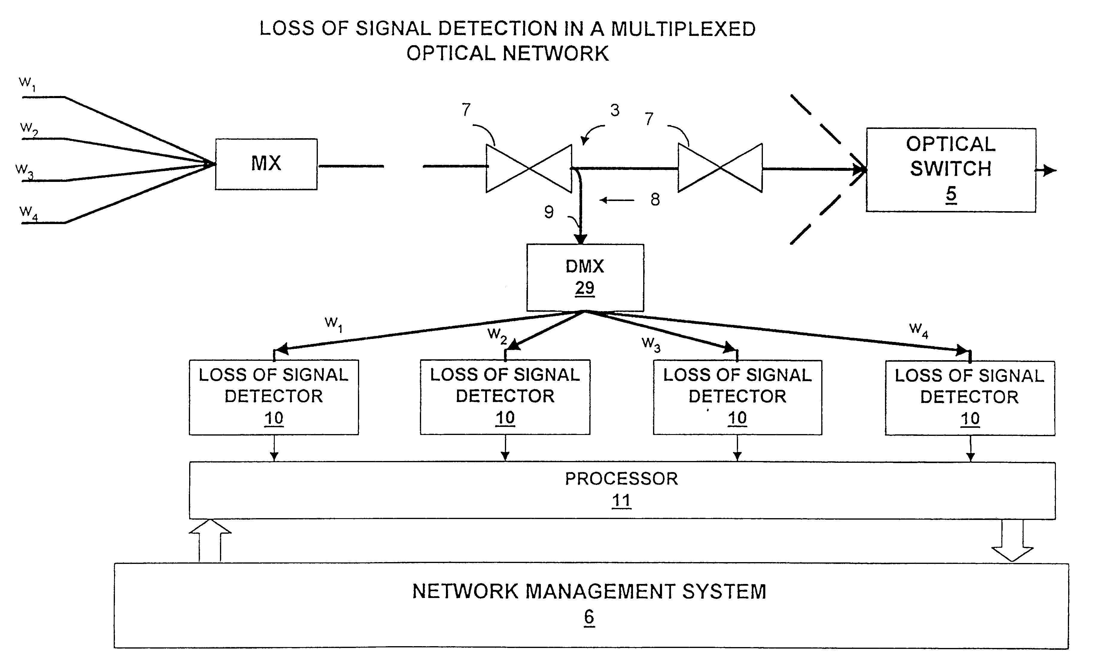
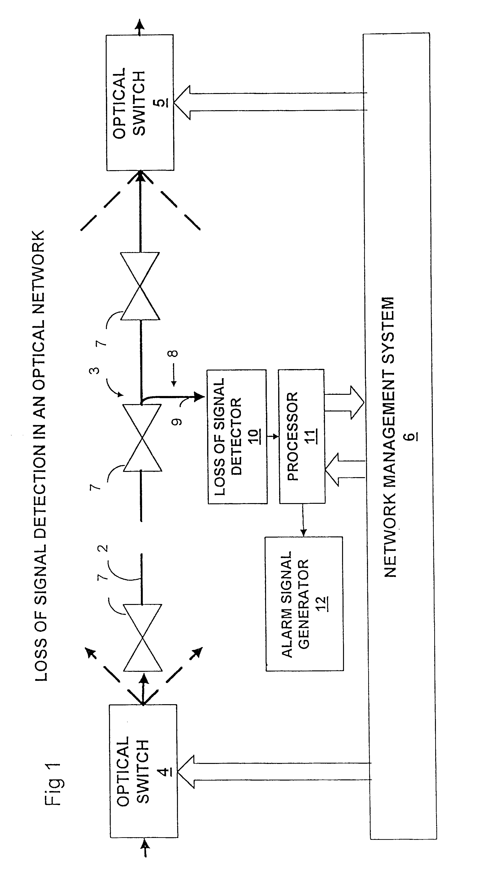
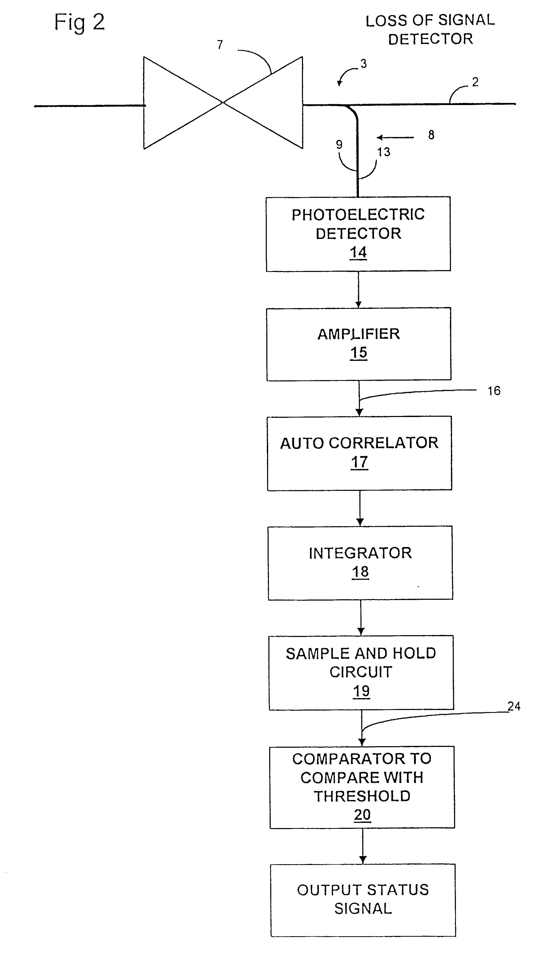
The loss of signal detector of FIG. 10 comprises an optical tap 8 deriving an optical tap signal 9 from a data signal carrying waveguide 2. Photoelectric detector 14 produces an electrical signal output which is amplified by a transimpedence amplifier 15 having a bandwidth 10 MHz. This bandwidth is considerably less than the bandwidth required to fully detect the signal since the bit rate frequency will typically be of the order of several GHz.

The amplifier 15 outputs a monitor signal 16 which is input to a band pass filter 40 and, in parallel, is also input to a low pass filter 41. The band pass filter 40 outputs a band pass filtered signal 42 which is filtered with lower and upper cut off frequencies of f.sub.1 and f.sub.2 respectively, f.sub.1 being selected to be above DC(zero frequency) and f.sub.2 ...

first embodiment

the present invention described above with reference to FIGS. 1 to 9 is concerned with a synchronous communications system in which an auto-correlator is used to detect a periodically occurring feature of the digitally coded data stream in the form of a series of bits forming framing bytes, as defined by the synchronization protocol.

Typically there may be other features of periodically recurring bit structures such as pointers to specific data areas within frames so that, where such further features are present, pronounced peaks in the power spectral density may occur at harmonics of the frame rate frequency.

It may therefore in some cases be preferable to carry out correlation at one of these harmonics of the frame rate frequency.

The loss of signal detector of the second embodiment described above with reference to FIG. 10 processes the monitor signal such that the characteristic measured is representative of the power of the optical signal in the defined bandwidth normalized relati...


PUM


Abstract

Loss of optical signal is detected in a synchronous communications system by detecting features of a monitor signal occurring at a detection frequency corresponding to the frame rate. Since the frame rate is substantially less than the bit rate, monitoring and detection can be performed at a lower bandwidth than the bit rate. An auto-correlation circuit utilises delays which are an integral multiple of the frame rate and produces a detection value which is compared with a threshold value. Alternatively, detection may be based on a power measurement of a band pass filtered monitor signal by setting the lower bandwidth limit above zero frequency and normalizing the measurement of power relative to an average power measurement. A loss of signal may then be detected by a change in power measurement relative to a threshold and can be used for asynchronous systems as well as synchronous systems. Loss of signal detection may be utilised to control an optical switch to re-route optical signals and generate alarm signals. The use of such detection in all optical networks avoids the requirement for electronic processing at the bit rate as a means of detection of loss of signal.

Description

This invention relates to the detection of a loss of signal condition in an optical communications system and in particular, but not exclusively, to the detection of a loss of signal condition in an all optical synchronous communications network.BACKGROUND TO THE INVENTIONExisting optical communications networks comprise a large number of system elements connected by optical fibres. A defect in such a network resulting in a loss of signal can be detected at a receiver by digital processing of the received signal bits after photoelectric conversion as described for example in U.S. Pat. No. 5,563,893 and U.S. Pat. No. 5,572,515. The majority of modern communications networks are synchronous communications systems conforming to frame format specifications such as those defined in accordance with the SONET standard specified by the American National Standards Institute (T1.105-199X, "American National Standard for Telecommunications--Digital Hierarchy--Optical Interface Rates and Format...

Claims


Application Information

Patent Timeline
Patent Type & Authority Patents(United States)
IPC IPC(8): H04B10/08
CPCH04B10/077H04B10/0771H04B10/0775H04B10/079H04B10/0793H04B10/07955H04B2210/071
Inventor HARDCASTLE, IANROBERTS, KIM BRYON
Owner CIENA
Why Eureka
Try Eureka