
Positional information providing system and apparatus

Inactive Publication Date: 2001-01-23
TOYOTA JIDOSHA KK
View PDF11 Cites 300 Cited by
  • Summary
  • Abstract
  • Description
  • Claims
  • Application Information

AI Technical Summary

Benefits of technology

Furthermore, the information regarding the above-mentioned landmark can be made to include the shape and type of the relevant landmark. An example of landmark type for roads is the route number or name to specify a road, such as national route 1 or Keihin route 3. On the basis of information on type, the number of landmarks to be searched by shape can be reduced and processing in a short time becomes possible.
According to this configuration, sending route information from the above-mentioned reference point to the above-mentioned specific position (facility) enables a map to be sent with more detail than the map database held in the terminal, thus allowing the facility position to be displayed in more detail.
Furthermore, in the various above-mentioned information provider systems, the peripheral landmarks that the above-mentioned position information generating means extracts can be two mutually connected roads positioned to sandwich the specific position (facility) of the information to be provided. According to this configuration, the display accuracy of the facility of the information to be provided can be improved.
It is preferable for the above-mentioned information center to also transmit the absolute position data during transmission of the relative position data, the above-mentioned terminal to specify the link close to the absolute position data existing in the terminal map database during a retransmission request, and the above-mentioned information center to transmit the relative position data using the specified link in the retransmission request. In order for the terminal side to specify a link to be used by the relative position data, the relative position data that used the link must exist in the map database at the terminal. Therefore, the transmission of reliable position information can be achieved from retransmission.
It is preferable for the information center to use data on the shape of the link to be transmitted as relative data using the link which exists in the terminal map database. With the relative data using the link which exists in the terminal map database in this manner, correct relative position relationships of new links and already existing links can be maintained.

Problems solved by technology

In the relative position with the above-mentioned landmark, problems arise, such as the above-mentioned facility being incorrectly displayed on the opposite side of the road, and besides the above-mentioned road, a railroad track, a river, a coastline, and so forth are landmarks.
In the case of a river, which can be crossed only at a bridge, if a facility is displayed on the opposite side of its actual position and the destination is incorrect, the bridge must be crossed in order to return to the correct position and much time will be wasted.
In the case of a coastline, there is the possibility of having an unnatural display in which the facility to be the destination is shown in the middle of the ocean.

Method used


Image

  • Positional information providing system and apparatus
  • Positional information providing system and apparatus
  • Positional information providing system and apparatus

Examples


first embodiment

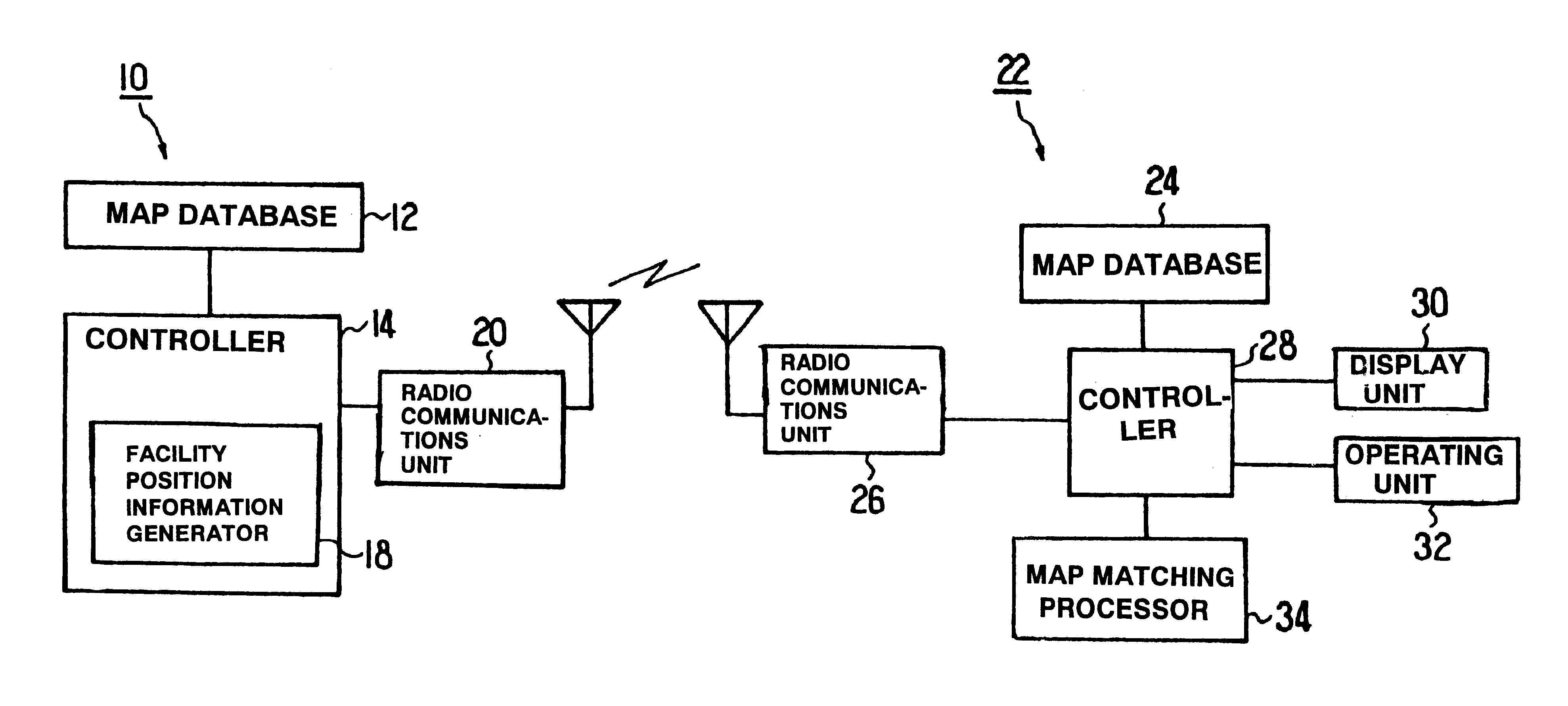
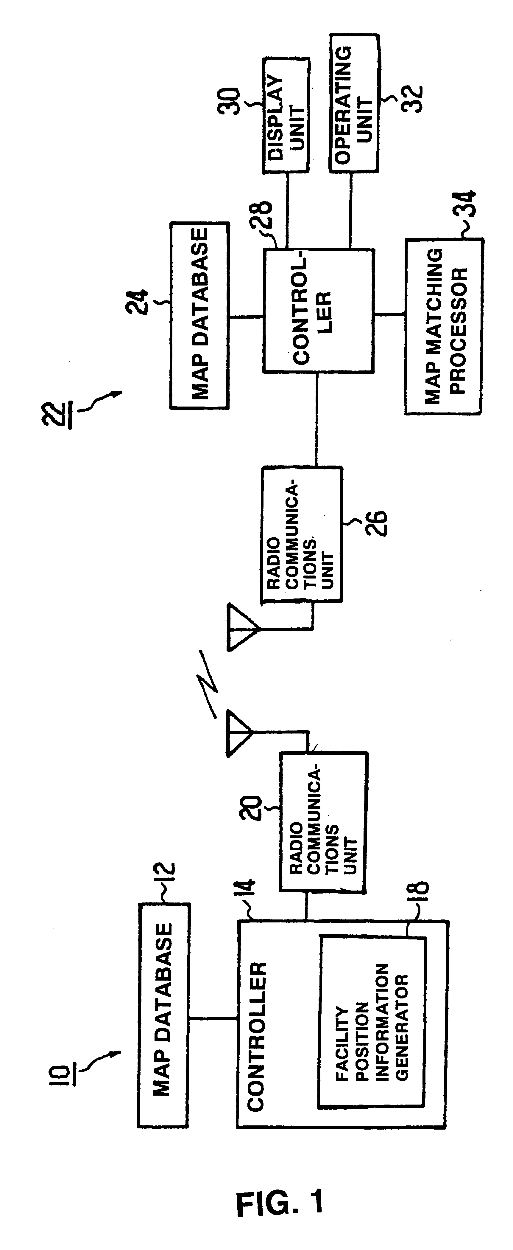
FIG. 1 shows a simplified configuration of the first embodiment. An information center 10 has a map database 12 for storing information necessary to display a map, such as the information on topography of rivers and coastlines and on structures of roads, bridges, and buildings. This map database 12 can also store information regarding the above-mentioned structures, and if the structure is a parking lot, for example, information on the parking lot's capacity as well as the present number of parked cars. The information center 10 has a controller 14 for reading out information from the map database 12 in accordance with an information request of a terminal to be described later. When there is a request for information regarding a certain facility from the terminal, the controller 14 has a facility position information generator 18 which extracts from the map database 12 a predetermined number of information items regarding landmarks in linear form on the map notation, such as rivers,...

second embodiment

General Configuration

FIG. 9 is a block diagram showing a configuration of the position information provider system to which the second embodiment concerns. A vehicle 110 is provided with a navigation controller 112 for performing various types of data processing. To the navigation controller 112 is connected a GPS device 114. The GPS device 114 detects the present position of the vehicle 110 by receiving radio waves from artificial satellites. It is also preferable to use a DGPS (differential GPS) device for detecting the present position with greater accuracy by obtaining error information, such as from FM multiplexed broadcasts.

To the navigation controller 112 is connected a map database 116. The map database 116, which may be based on CD-ROM, stores map information of the entire country of Japan. In the present embodiment, the map database 116 stores relatively simple map information since information is obtained from an external information center 130. To the navigation controll...


PUM


Abstract

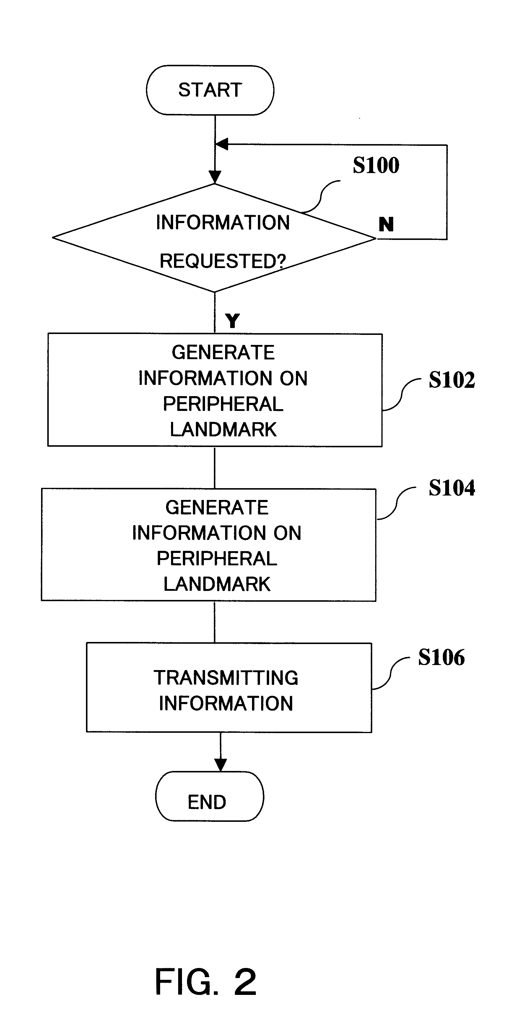
When information regarding position of a facility, such as a parking lot, is requested from a terminal (22), an information center (10) supplies position information to the terminal (22) as a relative position using a landmark, such as a neighboring road. The terminal (22) computes a shift from a position of a landmark in a local map database (24) and a position of a received landmark in a map matching processor (34), and corrects the facility position. If the landmark has not been stored in the map database (24) at the terminal (22), relative data based on another road is resent.

Description

The present invention relates to a system for transmitting desired information to a terminal from an information center in response to a request from the terminal, and more particularly to a facility information provider system for providing information regarding a certain facility.The present invention further relates to a position information provider system and a position information provider apparatus for recognizing absolute positions as position data relative to roads.Heretofore, navigation apparatuses are known as apparatuses for route guidance in vehicles. These navigation devices basically function by continuously detecting a present position and displaying it on a map. They contain a GPS (global positioning system) apparatus for detecting the present position and a map database for storing map data. Furthermore, by entering a destination, the navigation apparatus searches for an optimum route from the present position and also guides the vehicle in a set travel route in th...

Claims


Application Information

Patent Timeline
IPC IPC(8): G01C21/28G01C21/30G09B29/10
CPCG01C21/30G09B29/106G01C21/367G01C21/387
Inventor ISHIHARA, FUMINARIKANEMITSU, HIROYUKI
Owner TOYOTA JIDOSHA KK
Learn More