Lathes

a technology of lathes and sleeves, which is applied in the direction of turning apparatuses, large fixed members, sleeve/socket joints, etc., can solve the problems of adverse interference with the vacuum hose and the attachments connected thereto, and the prior art lathes do not enable an operator to effectively and safely gain access to all surfaces of an articl

Inactive Publication Date: 2001-01-30
CADDAYE ROBERT JOHN +1
View PDF11 Cites 17 Cited by
  • Summary
  • Abstract
  • Description
  • Claims
  • Application Information

AI Technical Summary

Benefits of technology

The lathe bed is preferably slidably affixed to a rotatable turntable. Preferably the lathe bed can be rotated up to 360.degree. in a horizontal plane about a vertical axis and can also be moved towards or away from the headstock. In this way larger blanks can be readily accommodated.
In this way direct alignment along a working axis between the headstock and tailstock can be maintained despite the position of the lathe bed in relation thereto.
The lathe can preferably contain an auxiliary bed positioned to one side of the headstock. The auxiliary bed has a similar cross sectional configuration to the lathe bed so that moveable components such as the tool rest can be moved along and repositioned therein. In this way a lathe operator can work on all surfaces of an object without having to remove the object from the headstock.
In addition the vacuum system described requires no contact between metal components thereby enhancing component durability.

Problems solved by technology

Despite advances in the art of the type mentioned there remain practical disadvantages.
For example, prior art lathes do not enable an operator to effectively and safely gain access to all surfaces of an article to be worked on.
While this may allow an operator working access to a backside of an article to be worked on, further practical problems arise because in the reverse position an operator will be required to work left handed as a spindle is effectively rotating in an opposite direction.
Further attempts to overcome this problem have involved a rotatable headstock, however this type of arrangement still requires an operator to substantially change position and can adversely interfere with vacuum hoses and attachments connected thereto.
Further disadvantages of the prior art lathes include an inability to enable efficient turning of a large blank.
In particular if a headstock is able to be rotated to accommodate a large blank, the tailstock cannot be properly brought into an alignment position.
In this situation the blank is not properly supported not is it safely balanced.
As a result significant vibrations will occur in prior act lathes which are hazardous for lathe operators.
This type of arrangement is potentially very dangerous since if there is even any slight imbalance or misalignment the vacuum tubing connected to the lathe spindle can be dislodged.
At relatively high rates of spindle rotation any dislodgement of vacuum tubing at such high rates may well be fatal to an operator.
In many instances this type of attachment is extremely unsafe because it relies on an external rotating extension of a spindle to permit use of a commercially available rotary union to provide the means of inducing vacuum through the spindle to a chuck.
Finishing and polishing operations usually carried out on a vacuum plate type chuck are made at relatively high spindle RPM (800-2000 RPM) and at such speeds a hose can cause severe injury or death if this rotary union seizes up causing the hose to break off and rotate in a whip like manner.

Method used


Image

  • Lathes
  • Lathes
  • Lathes

Examples


Embodiment Construction

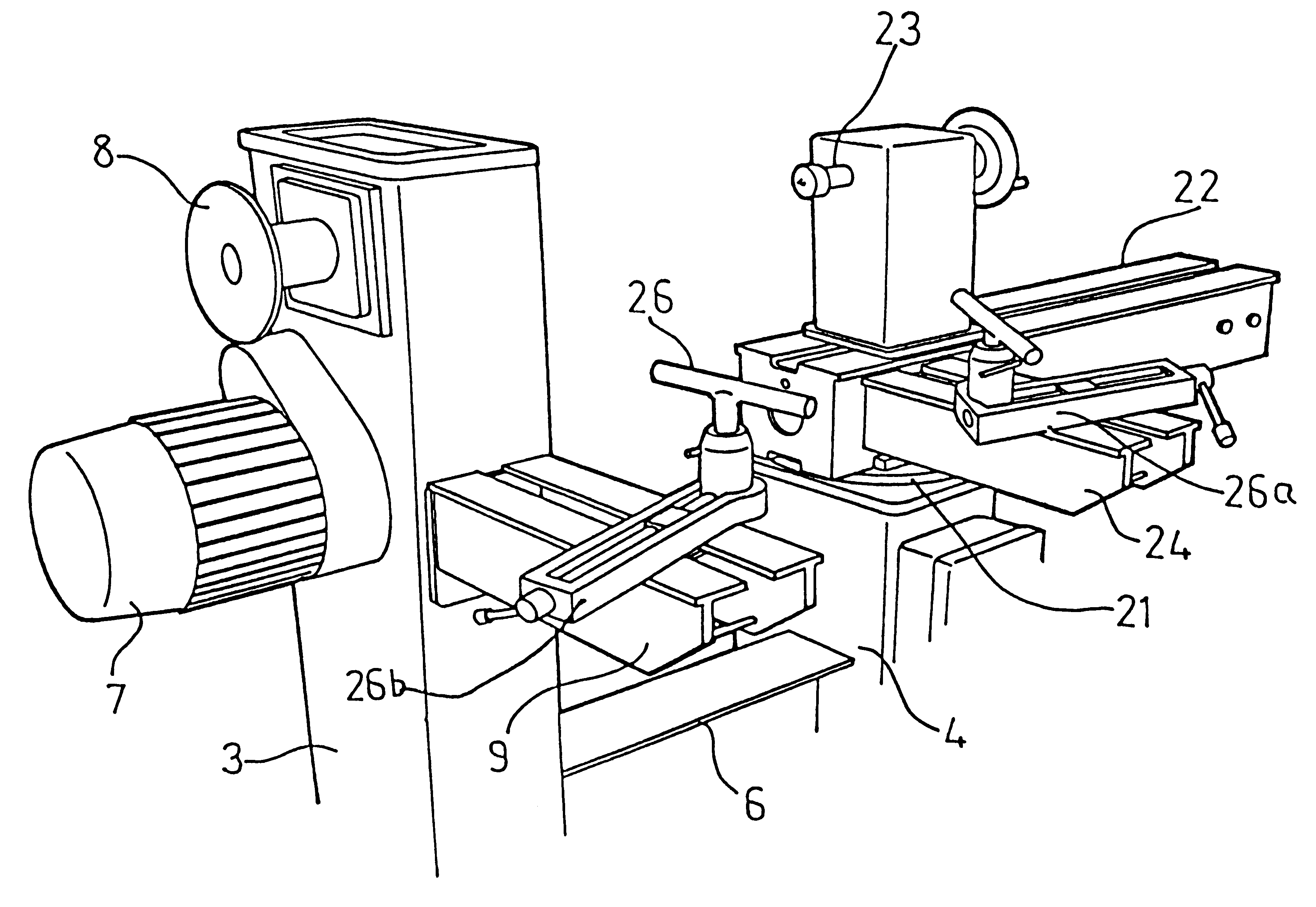
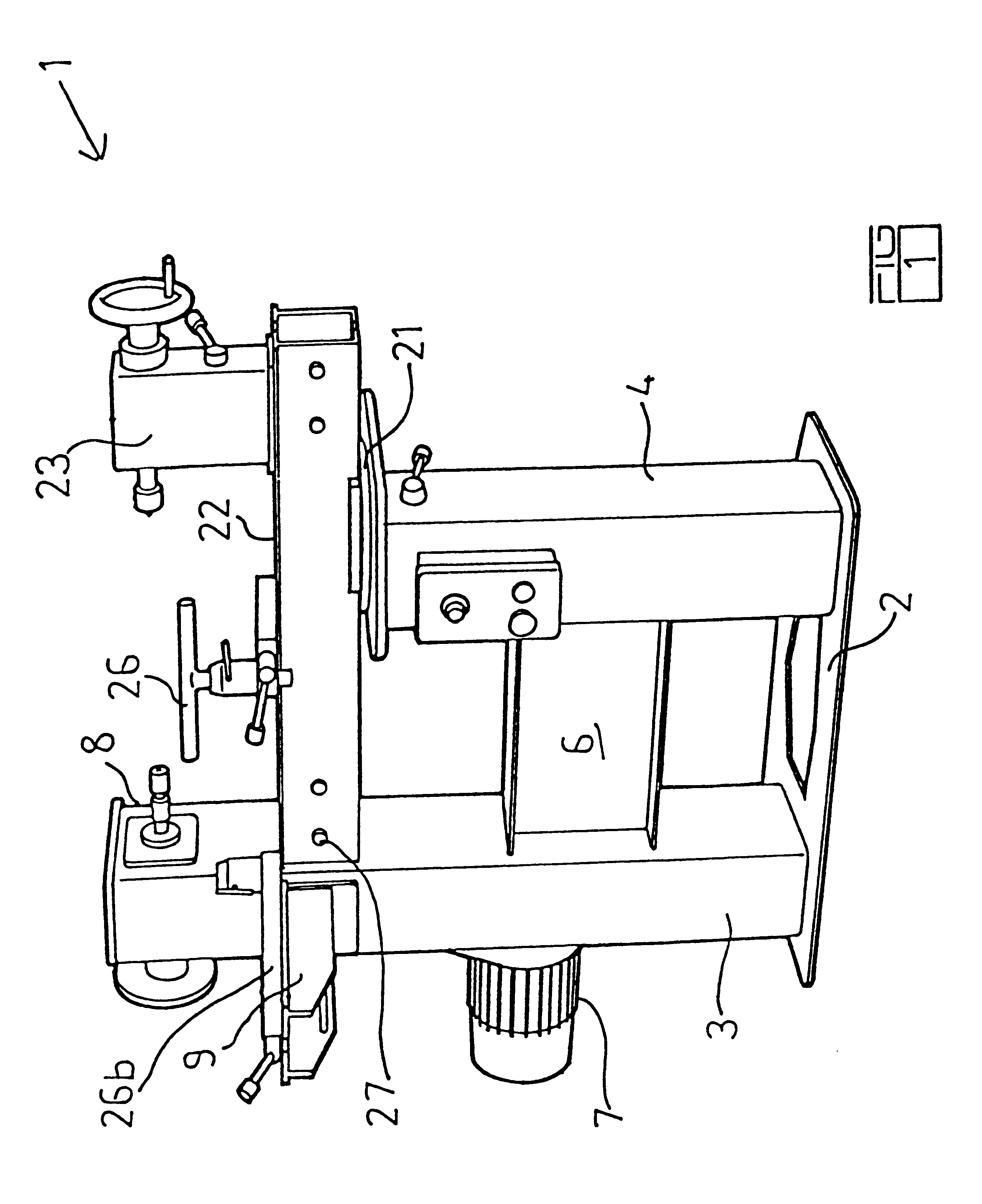
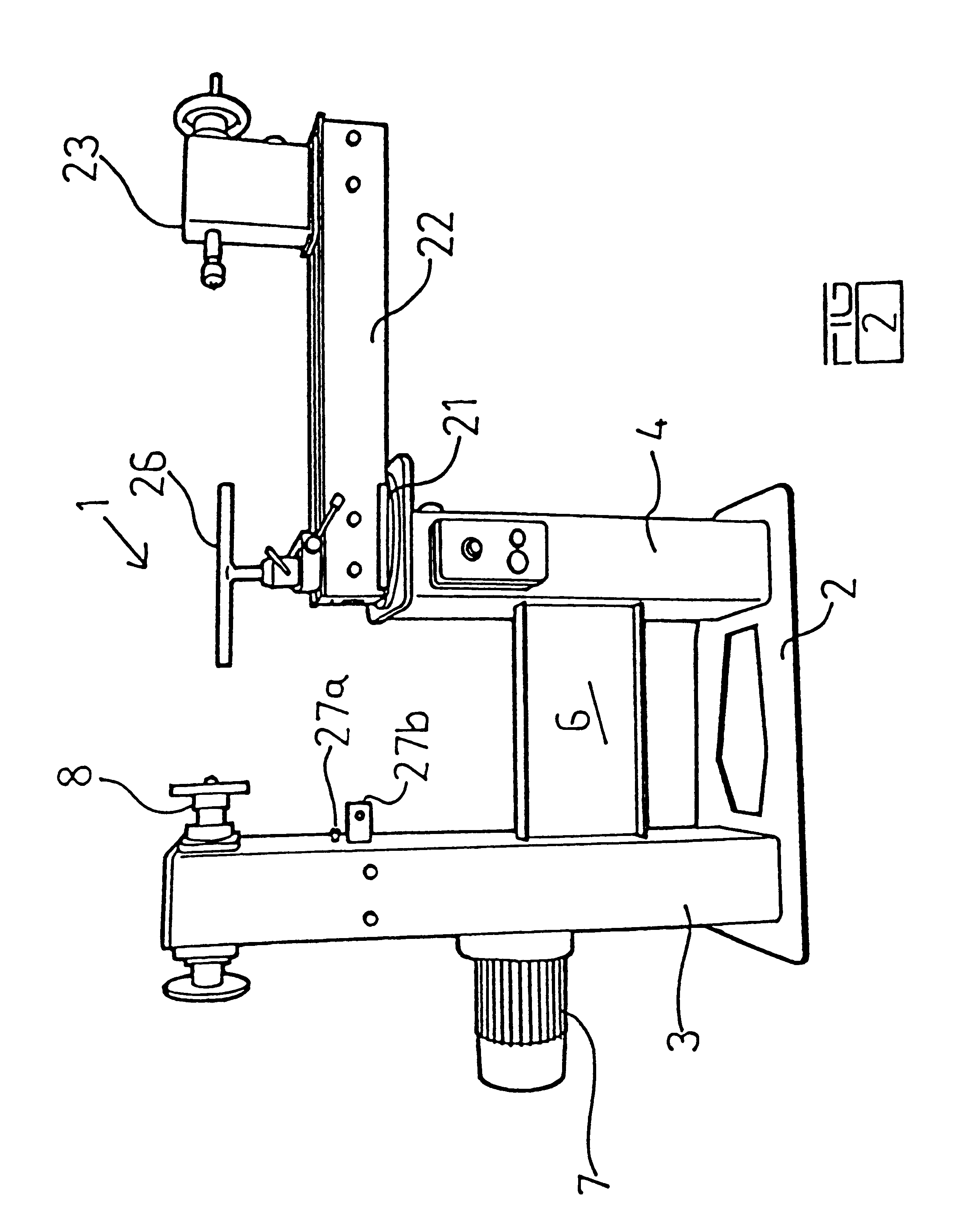
Preferably the lathe bed is manufactured in two symmetrical longitudinal halves which are bolted or welded together.

The lathe bed is preferably slidably affixed to a rotatable turntable. Preferably the lathe bed can be rotated up to 360.degree. in a horizontal plane about a vertical axis and can also be moved towards or away from the headstock. In this way larger blanks can be readily accommodated.

Preferably the lathe bed contains a centrally located groove along its length forming a track in which a tailstock and tool rest can be slidably moved or rotated therein in a horizontal plane about a vertical axis.

Preferably the tailstock is able to be slidably moved in both a forward and backward direction along the lathe bed and is rotatable about a vertical axis within the lathe bed. More preferably the tailstock can be swivelled and realigned with the headstock so as to maintain a central working axis.

In this way direct alignment along a working axis between the headstock and tailstock...


PUM

PropertyMeasurementUnit
right anglesaaaaaaaaaa
angleaaaaaaaaaa
vacuumaaaaaaaaaa

Abstract

The present invention therefore provides in one aspect a lathe including:a headstock comprising a lathe spindle;a tailstock; anda lathe bed wherein the lathe bed is mounted to be rotatable in a horizontal plane about a vertical axis.In a second aspect of the invention there is provided a lathe including:a headstock comprising a lathe spindle passing through a hollow column and within the hollow column means adapted to safely connect a vacuum to the interior of the lathe spindle;a tailstock; anda lathe bed wherein the lathe bed is mounted to be rotatable in a horizontal plane about a vertical axis.In a third aspect of the invention there is provided a lathe including:a headstock comprising a lathe spindle passing through a hollow column and within the hollow column means adapted to safely connect a vacuum to the interior of the lathe spindle;a lathe bed wherein the bed is mounted to be rotatable in a horizontal plane about a vertical axis; anda tailstock adapted to rotate 360° through its normal central location to permit alignment with the headstock spindle axis regardless of angular location of the lathe bed about its vertical axis.

Description

This invention relates to lathes.BACKGROUND TO THE INVENTIONThere is a need to provide a lathe having multiple adaptability for various uses but in particular for use in wood turning although the lathe of the present invention may be used in respect of other operations with respect to other materials such as metals and composite materials.Lathes and cutting machines are known for turning rotationally symmetrical elements such as wooden spindles or balustrades. Generally a work piece is mounted in chucks and is spun and a knife or set of knives are urged towards the work piece causing wood outside the desired profile to be chipped away.Wood lathes are known, and most lathes are cast having a fixed bed, a headstock and a tailstock. There have been known lathes hat beds which can be raised or lowered, and moved towards or away from a headstock along a centreline axis between a headstock and a tailstock. Indeed it has been known for a lathe to include a rotatable headstock and even beds...

Claims


Application Information

Patent Timeline
Patent Type & Authority Patents(United States)
IPC IPC(8): B23Q1/48B23B3/06B23B3/00B23Q1/00B23Q1/01B23Q1/25B27C7/00B27C7/06
CPCB23B3/06B23Q1/0027B23Q1/015B23Q1/4809B27C7/00B27C7/06Y10T82/25Y10T82/2564Y10T82/2566Y10T279/11Y10T82/2552
Inventor CADDAYE, ROBERT JOHNCADDAYE, MARILYN JEANETTE
Owner CADDAYE ROBERT JOHN
Why Eureka
Try Eureka