Magnetic/air transportation system

a magnetic/air transportation and air technology, applied in the field of mass transit transportation system or cargo transportation system, can solve the problems of disturbing the peace of the surrounding area, generating significant amount of loud noise from engines, and affecting the environmental protection of the area

Inactive Publication Date: 2001-01-30
HARDING LOU O
View PDF7 Cites 47 Cited by
  • Summary
  • Abstract
  • Description
  • Claims
  • Application Information

AI Technical Summary

Benefits of technology

It is yet another object of the present invention to provide a transportation system that is quiet and which does not locally emit any fumes or exhaust in conjunction with the traveling vehicle.

Problems solved by technology

Despite the advantages of the foregoing transportation means currently known in the art, they are also subject to several drawbacks.
For example, in the running of locomotive trains and tractor trailer truck rigs, chemical and / or fossil fuel pollution occurs through the exhaust of the burning of fuel in order to operate internal combustion engines.
Additionally, such internal combustion engines often generate significant amount of loud noise, disturbing the peace of the surrounding area.
This is true even with the use of associated mufflers or the like, which decrease the energy efficiency of such internal combustion engines.
Generally, the infrastructure to support locomotives and / or truck rigs is significantly expensive, not only to initially construct, but also to maintain in an ongoing basis.
A complicated switching system is present in the Mandros patent, indicating that the construction of such a system would require significant maintenance as well as a significant, if not costly, construction.

Method used


Image

  • Magnetic/air transportation system
  • Magnetic/air transportation system
  • Magnetic/air transportation system

Examples


Embodiment Construction

)

The detailed description set forth below in connection with the appended drawings is intended as a description of presently preferred embodiments of the invention and is not intended to represent the only forms in which the present invention may be constructed and / or utilized. The description sets forth the functions and the sequence of steps for constructing and operating the invention in connection with the illustrated embodiments. However, it is to be understood that the same or equivalent functions and sequences may be accomplished by different embodiments that are also intended to be encompassed within the spirit and scope of the invention.

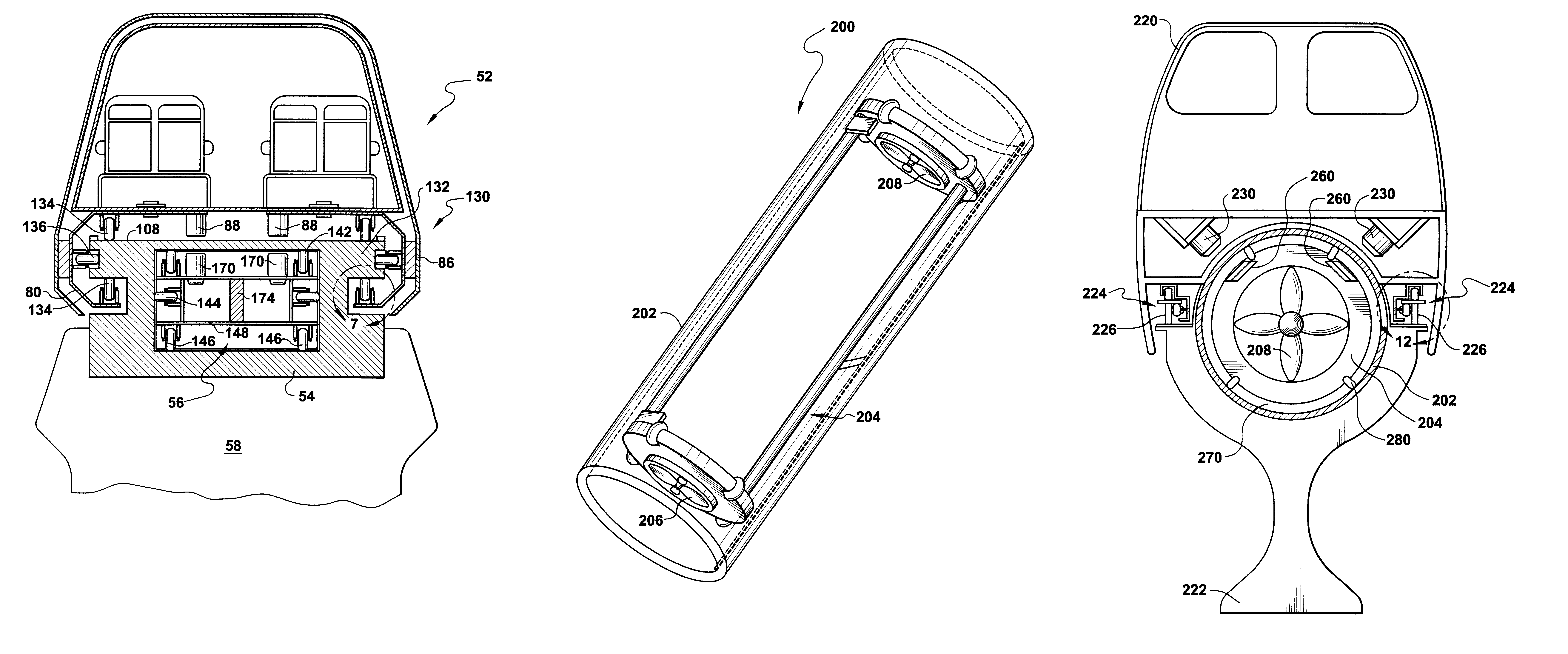
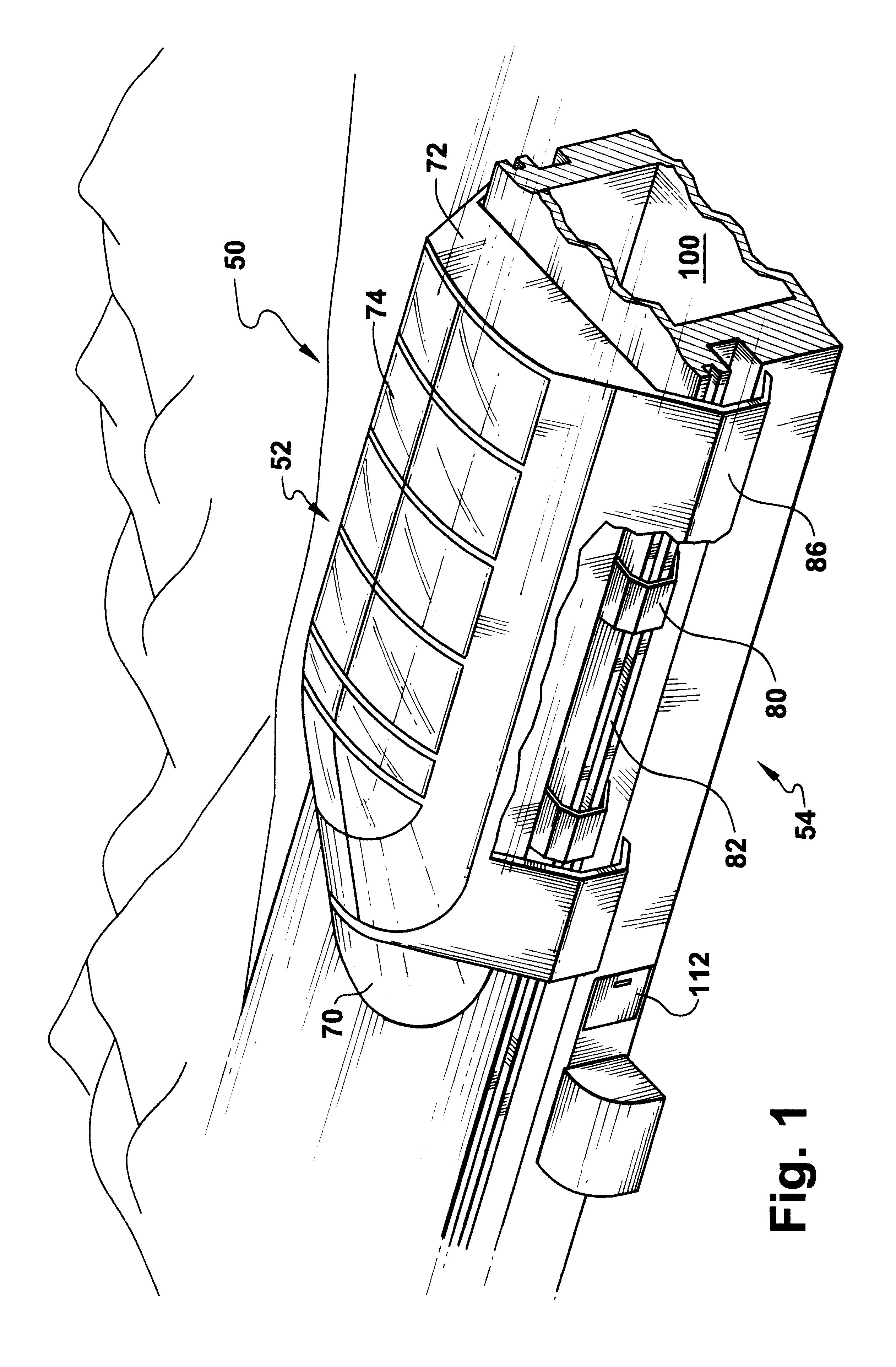
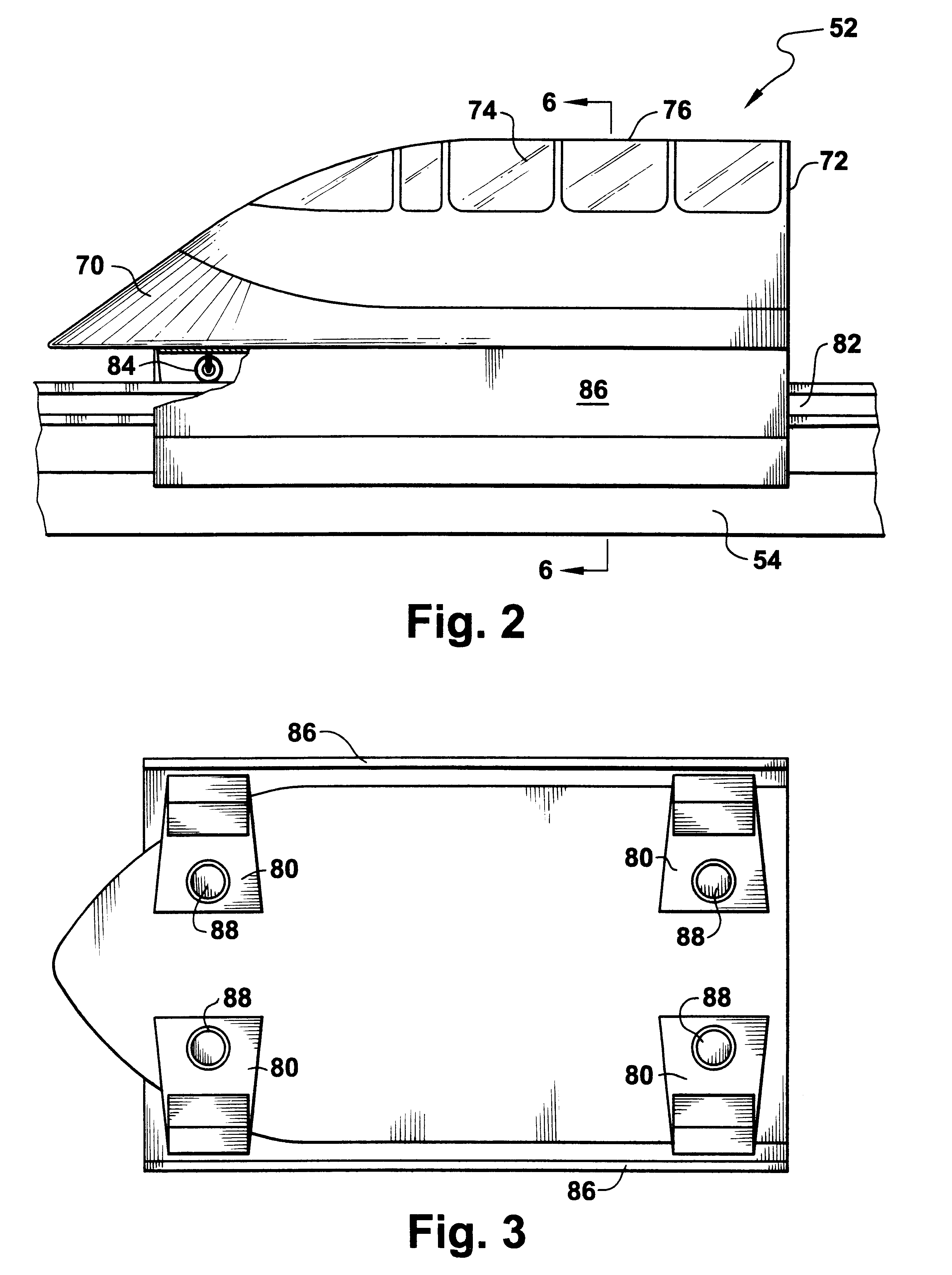
As shown in FIG. 1, two (2) primary components of the transportation system 50 of the present invention are the transported vehicle or car 52 and the pressurization passageway, pressurization vessel, carrier conduit, or carrier channel ("carrier conduit") 54. As shown in FIGS. 6, 8, and 9, the third component of the transportation system 50 ...


PUM


Abstract

A transportation system uses a carrier conduit in the form of a long tube or channel in order to drive a vehicle by air pressure. A carrier having end plates obstructs the travel of air through the carrier conduit. Pressure differentials formed within the carrier conduit serve to propel the carrier through the carrier conduit. By rollably supporting the carrier within the carrier conduit, friction is reduced between the carrier conduit and the carrier. The carrier may be magnetically coupled to a vehicle having vanes and a set of track- or rail-engaging wheel assemblies on vanes. The vanes may pivot upon the vehicle and serve to allow the vehicle to rollably or slidably couple to the carrier conduit track. The motion of the carrier serves to propel the vehicle along the carrier conduit track as the vehicle is magnetically coupled to the carrier. Composite materials used to construct the carrier conduit may allow for such magnetic coupling without the interference that might occur through the use of ferromagnetic materials or the like. The carrier conduit may be mounted upon pillars or pylons and sources of pressure may either be present at either end of the carrier conduit, distributed at propitious points there along, or incorporated into the carrier.

Description

1. Field of the InventionThis invention relates to transport systems, and more particularly mass transit transportation system or cargo transportation systems that use air pressure to propel the person or cargo carrier.2. Description of the Related ArtThe ability to move people or things from one place to another is both a necessity and a convenience in today's society. Transportation is a necessity for the easy delivery and distribution of goods and services. It is a convenience as discretionary travel or transport provides an enhanced quality of life.Ground transportation can be particularly pleasurable as it allows the individuals so traveling to enjoy the surrounding scenery. It is generally less expensive to transport goods by ground services than by air or sea.With respect to ground transportation, railroads, light rail, monorails, and subways are generally those best known for allowing travel in urban and other areas. Tractor trailer rigs, 18-wheel trucks, and cargo vans prov...

Claims


Application Information

Patent Timeline
Patent Type & Authority Patents(United States)
IPC IPC(8): B60V3/04B61B13/12B60V3/00
CPCB60V3/04B61B13/122
Inventor HARDING, LOU O.
Owner HARDING LOU O
Why Eureka
Try Eureka