Resonant sensor and method of making a pressure sensor comprising a resonant beam structure

a technology of resonant beams and pressure sensors, applied in the field of resonant sensors, can solve the problems of difficult manufacturing, complicated calibration, and the drawbacks of known sensors

Inactive Publication Date: 2001-02-06
ST JUDE MEDICAL COORDINATION CENT
View PDF18 Cites 76 Cited by
  • Summary
  • Abstract
  • Description
  • Claims
  • Application Information

AI Technical Summary

Problems solved by technology

However, the known sensors suffer from some drawbacks.
In particular calibration is fairly complicated and also the manufacture is not an easy task with fairly high rejection rates of finished products.
However, there are certain limitations to this structure, in particular the fact that the beam is a part of the composite diaphragm.
This will adversely affect the sensitivity of the sensor.
The transducers obtainable by the teachings therein suffer from a limitation in that they cannot be sufficiently miniaturized for certain applications, such as a pressure sensor for use in coronary vessels.
This is a very difficult operation if one wants to achieve a proper vacuum, as required for adequate resonance of the beam to occur.
Another drawback with this device is to be found in the selection of materials.
The prior art devices fail to meet these dimensional requirements, or they suffer from sensitivity limitations.

Method used


Image

  • Resonant sensor and method of making a pressure sensor comprising a resonant beam structure
  • Resonant sensor and method of making a pressure sensor comprising a resonant beam structure
  • Resonant sensor and method of making a pressure sensor comprising a resonant beam structure

Examples


Embodiment Construction

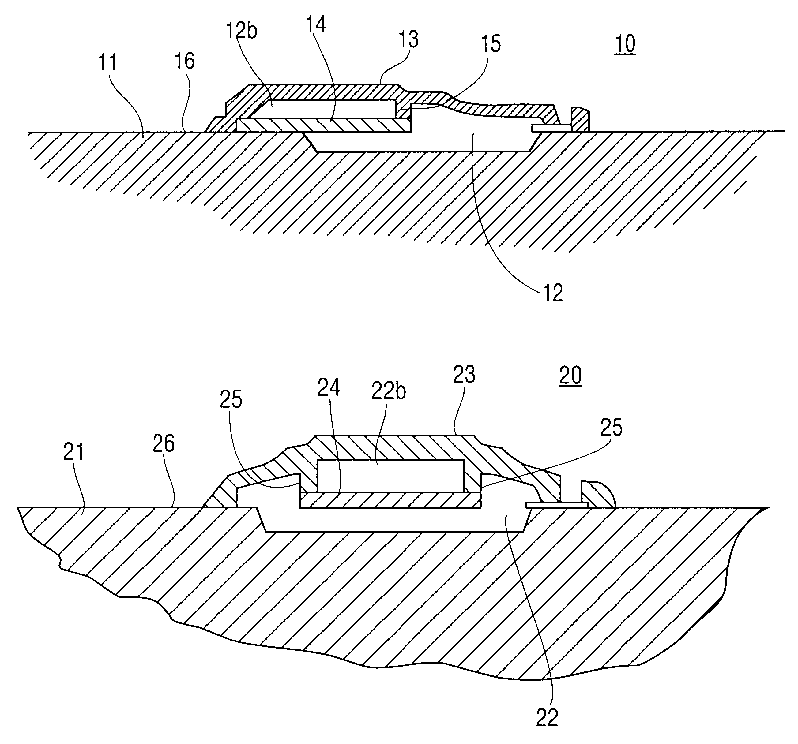
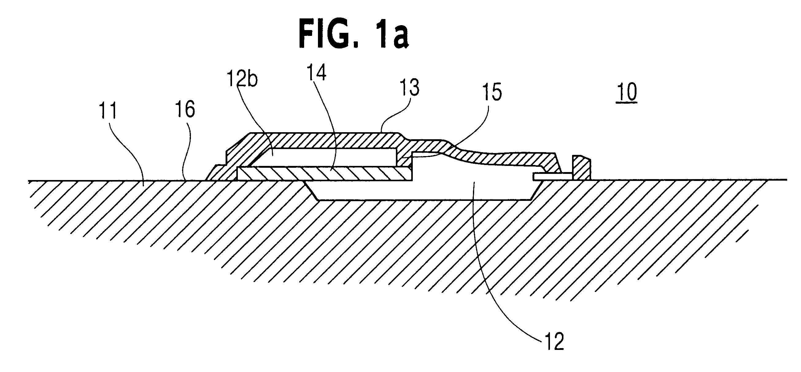
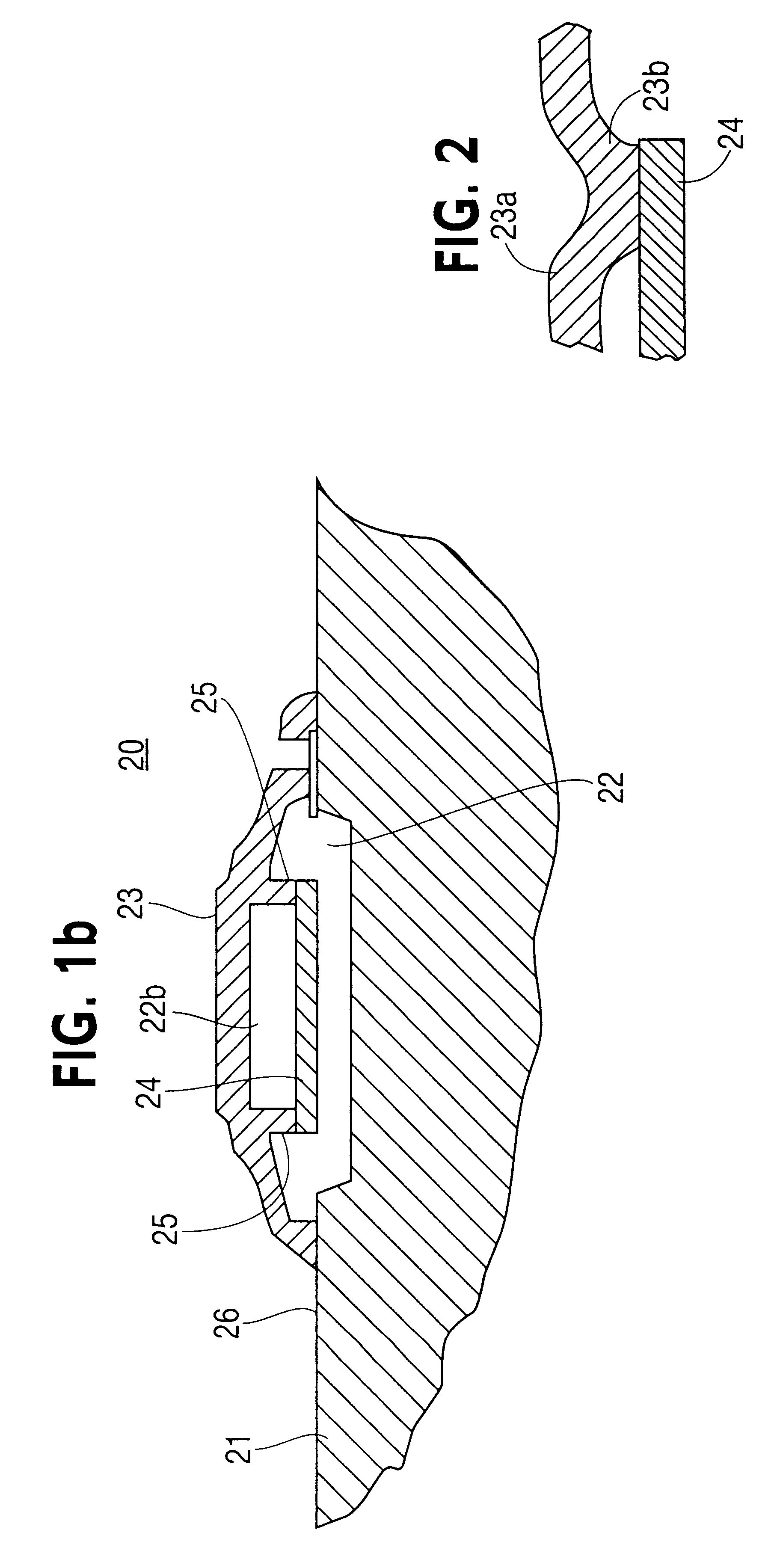
FIG. 1a shows a cross section of an embodiment of the present thin film resonant microbeam sensor device 10 according to the present invention. It comprises a substrate 11 of silicon, in which there has been formed a depression by surface micromachining, sacrificial oxide, etching and reactive sealing. Covering the depression there is a diaphragm 13 of amorphous silicon. In this embodiment, the diaphragm structure is slightly elevated from the upper surface 16, and thus a vacuum cavity 12, 12b is formed between diaphragm 13 and substrate 11. It would of course be conceivable to make a structure where the membrane is located essentially in the same plane as the surrounding substrate. Within the cavity 12 a resonant beam member 14 is provided suspended at one end of its ends by a suspension member 15 connecting the beam with the diaphragm 13, and at its other end attached to the substrate 11. Thus, the entire surface of the beam 14 is spaced from both the diaphragm 13 and the substra...


PUM

PropertyMeasurementUnit
thicknessaaaaaaaaaa
thicknessaaaaaaaaaa
thicknessaaaaaaaaaa

Abstract

A resonant microbeam pressure sensor is disclosed, comprising a microbeam suspended in a diaphragm in at least one point by suspension elements. Pressure applied to the diaphragm will cause the resonance frequency of the beam to shift. This shift is detectable and proportional to the pressure. The device is manufactured by surface micromachining.

Description

1. Field of the InventionThe present invention relates to the field of semiconductor and micromechanical devices and processing techniques therefor, and particularly to resonance sensors, and to the manufacture of resonating structures for such sensors for pressure measurements.2. Description of Related ArtUltra miniaturized sensors for minimal invasive use have become important tools in for example heart surgery and diagnosis during the last ten years. So far optical or piezoresistive principles have been employed and sensors based on these technologies are commercially available. However, the known sensors suffer from some drawbacks. In particular calibration is fairly complicated and also the manufacture is not an easy task with fairly high rejection rates of finished products. Therefore there is a search for new types of sensors and other means and methods of making ultra miniaturized sensors in an efficient and economic way.In U.S. Pat. No. 5,747,705 (Herb et al) there is discl...

Claims


Application Information

Patent Timeline
Patent Type & Authority Patents(United States)
IPC IPC(8): G01L9/00
CPCG01L9/0016G01L9/0017G01L9/0042
Inventor STEMME, GOERANKAELVESTEN, EDVARD
Owner ST JUDE MEDICAL COORDINATION CENT
Why Eureka
Try Eureka