Method of operating a multi-antenna pulsed radar system

Inactive Publication Date: 2001-02-06
AUTOMOTIVE DISTANCE CONTROL SYST
View PDF8 Cites 48 Cited by
  • Summary
  • Abstract
  • Description
  • Claims
  • Application Information

AI Technical Summary

Problems solved by technology

In view of the simultaneous transmitting and receiving operations, a rather high expense and effort is necessary for achieving an adequate decoupling

Method used


Image

  • Method of operating a multi-antenna pulsed radar system
  • Method of operating a multi-antenna pulsed radar system
  • Method of operating a multi-antenna pulsed radar system

Examples


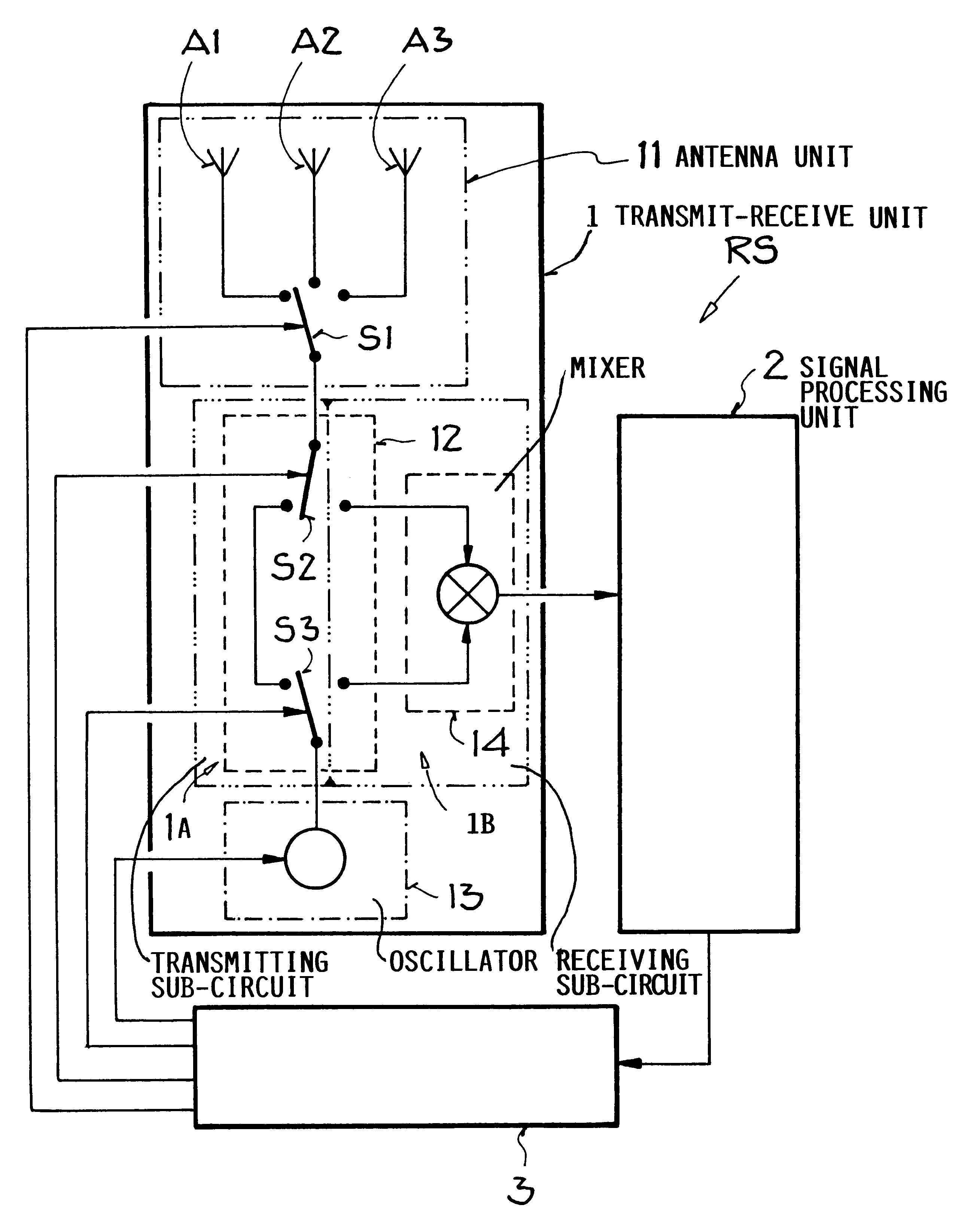
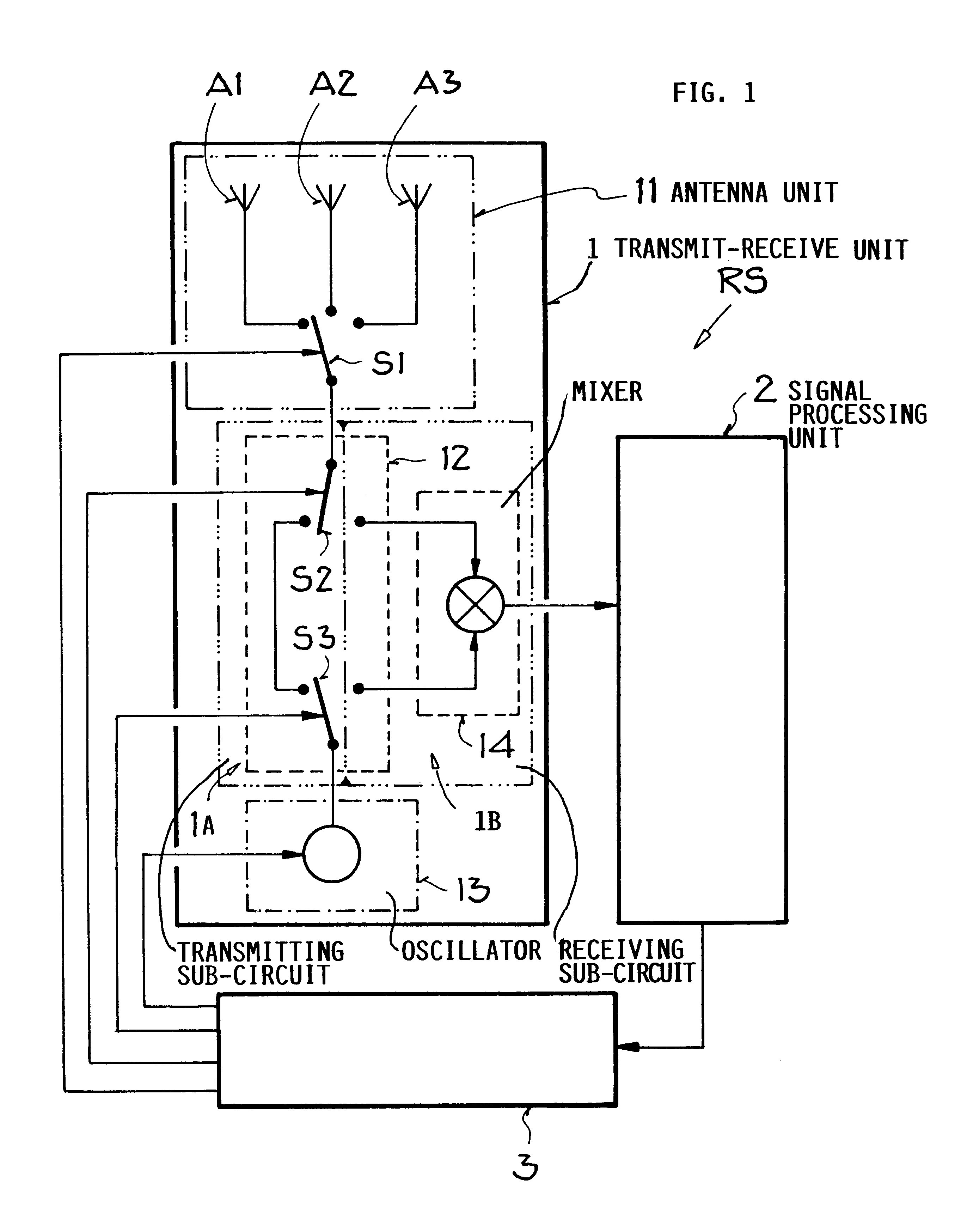
Embodiment Construction

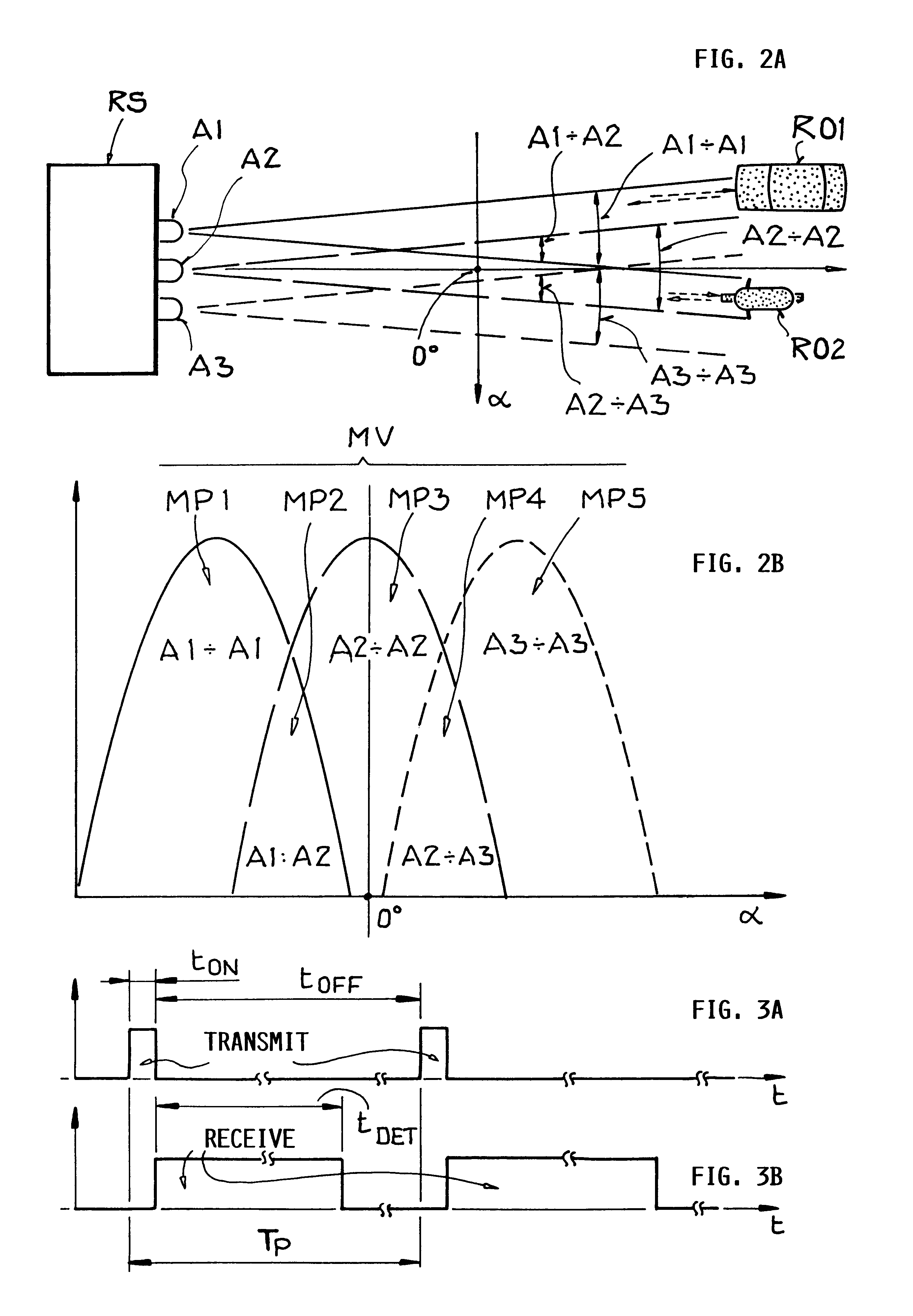
Distance sensors used in separation distance warning systems for motor vehicles must be able to determine the distance or range and in some cases the relative velocity of reflection objects located in the pertinent observation field, with high resolution and without ambiguity. These reflection objects may particularly be preceding, following, or approaching vehicles, pedestrians, or any other radar reflection objects present in the pertinent traffic field or observation area around the subject motor vehicle. For example, the desired unambiguous distance measuring range or monomode operation range may be 150 m (which is relatively small in comparison to other radar systems), the desired distance resolution may be 1 m, and the desired velocity resolution may be 1 km / h. Moreover, it is a constant goal to achieve a good angular resolution, i.e. a good separation and discrimination ability between different adjacent reflection objects, for example between several vehicles driving ahead o...


PUM


Abstract

A method for operating a radar system using at least two antennas provides an increased angular resolution for determining the angular position, radial velocity, and/or distance to a reflection object. A plurality of successive measuring phases are carried out in at least one measuring process. In each measuring phase, operation is repeatedly switched between a transmitting operation in which a transmitted signal pulse is emitted, and a receiving operation in which reflection signals are detected as received signals in the pulse pause interval between successive transmitted pulses. In at least one measuring phase, two different neighboring antennas of the radar system are used respectively as the transmitting antenna for emitting the transmitted signal and as the receiving antenna for detecting the reflected signal. In this manner, the respective receiving antenna monitors only the angular range of overlap between the emitted beam of the transmitting antenna and the field of view of the receiving antenna. The information provided by the detected signals in this overlapping angular range achieves an increased angular resolution. The method is particularly suitable for operating a separation distance warning system for a motor vehicle.

Description

PRIORITY CLAIMThis application is based on and claims the priority under 35 U.S.C. .sctn.119 of German Patent Application 198 29 762.9, filed on Jul. 3, 1998, the entire disclosure of which is incorporated herein by reference.The invention relates to a method for operating a pulsed radar system that uses at least two antennas for detecting or monitoring in different angular ranges, so as to determine the distance, the angular position, and / or the radial velocity of a reflection object or target object in the field being monitored. The invention further relates to a circuit arrangement for carrying out the method.BACKGROUND INFORMATIONIt is generally known to use radar systems for determining the distance or range from the radar system to moving or stationary target objects, and / or for determining the radial velocity or the relative velocity of such target objects. The radar systems are typically adapted for use in different distance ranges. The main field of use of such radar system...

Claims


Application Information

Patent Timeline
IPC IPC(8): G01S13/00G01S13/48G01S13/87G01S13/93G01S3/46G01S13/931
CPCG01S13/48G01S13/87G01S13/931G01S2013/9325
Inventor ADOMAT, ROLFWAIBEL, FRANZ
Owner AUTOMOTIVE DISTANCE CONTROL SYST
Why Eureka
Try Eureka