
Selective catalytic reduction processes using doped cerias

a catalytic reduction and selective technology, applied in the direction of metal/metal-oxide/metal-hydroxide catalysts, machines/engines, arsenic compounds, etc., can solve the problems of reducing the efficiency and generating backpressure, so as to achieve the no2 level, reduce the size, complexity, and cost of the exhaust treatment system

Inactive Publication Date: 2015-07-02
JOHNSON MATTHEY PLC
View PDF1 Cites 5 Cited by
  • Summary
  • Abstract
  • Description
  • Claims
  • Application Information

AI Technical Summary

Benefits of technology

The patent text describes a new type of catalyst for selective catalytic reduction (SCR) processes. These catalysts are made by adding niobia or tantala to ceria, which helps to increase the level of NO2 and improve the conversion of NOx. These catalysts can also be used for soot oxidation, making them ideal for SCRF® catalyzed filters and other exhaust treatment applications. Using these catalysts can reduce the size, complexity, and cost of exhaust treatment systems.

Problems solved by technology

The soot accumulates on the filter surface, generates backpressure, and eventually needs to be burned off at elevated temperatures.
Because most SCR catalysts are unable to withstand these high temperatures, separate systems are needed.
However, because space is limited, designers would like to combine the SCR and soot oxidation functions into a single, compact after-treatment unit, which is typically the DPF (see, e.g., U.S. Publ. No. 2010 / 0180580).
This difference in reactivity therefore limits the usefulness of known SCR catalysts for passive soot oxidation.
Although the strategy is effective, it decreases the overall amount of SCR catalyst that can be deposited on the filter and may limit the degree of NOx reduction possible.

Method used


Image

  • Selective catalytic reduction processes using doped cerias
  • Selective catalytic reduction processes using doped cerias
  • Selective catalytic reduction processes using doped cerias

Examples


example 1

Preparation of Niobia-Doped Ceria (3.2 wt. % Nb2O5)

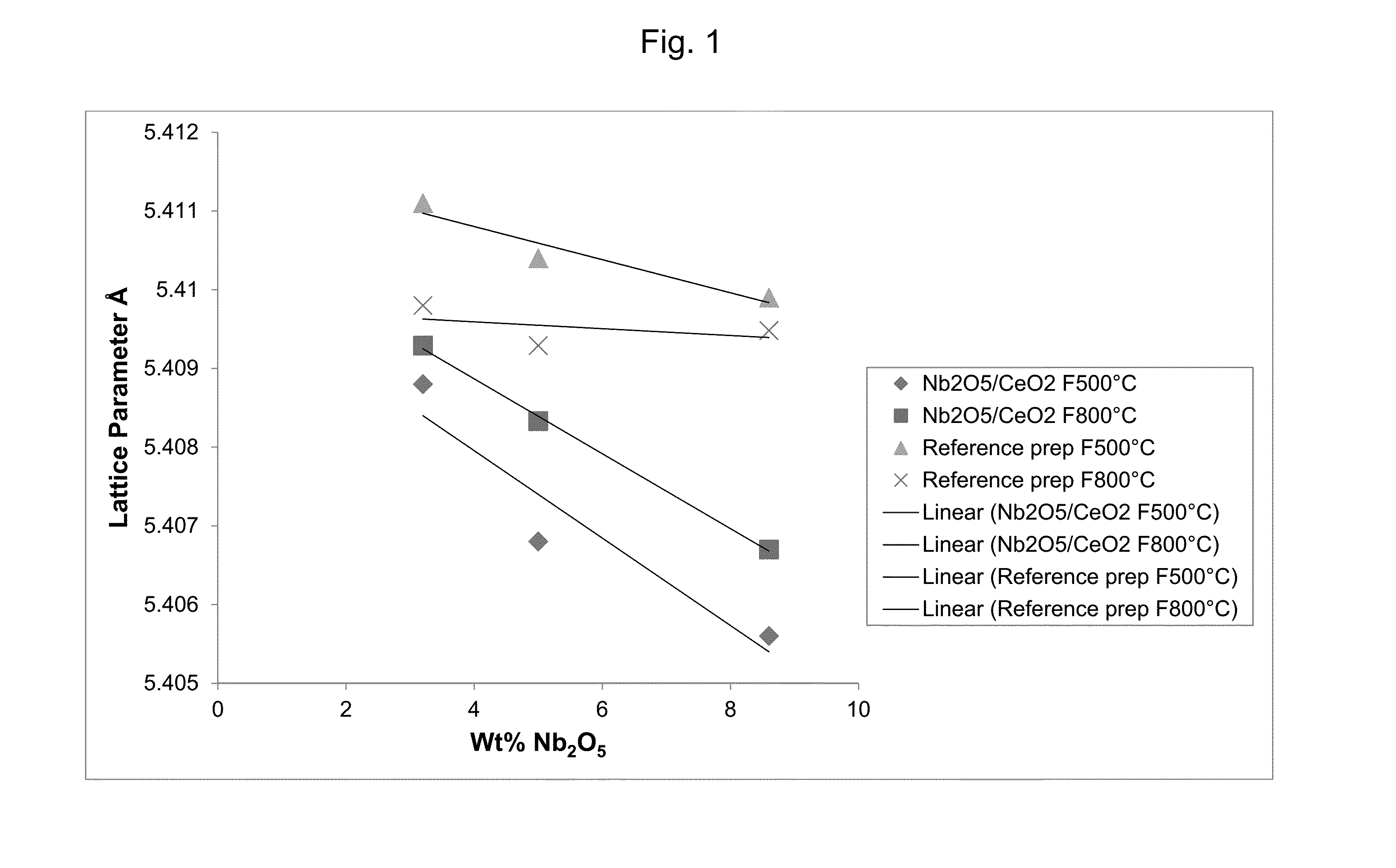
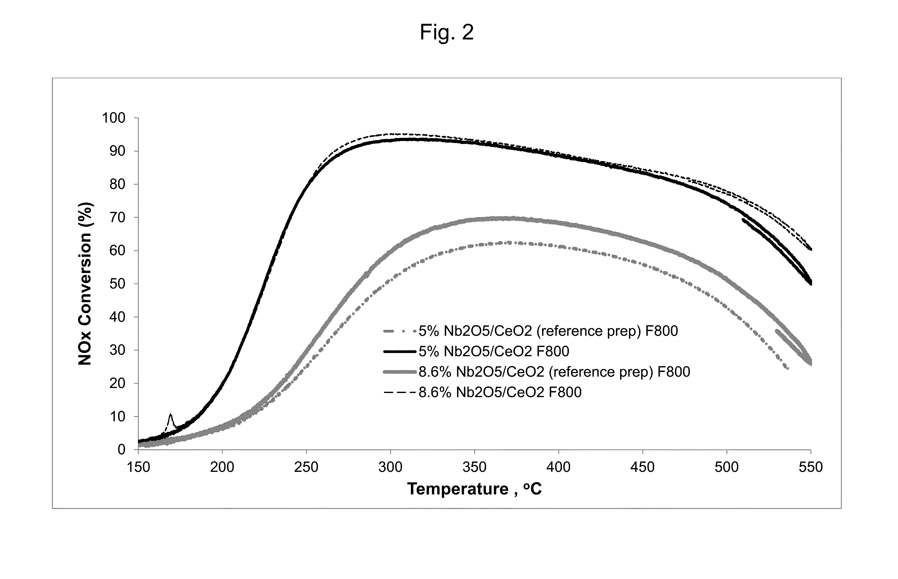
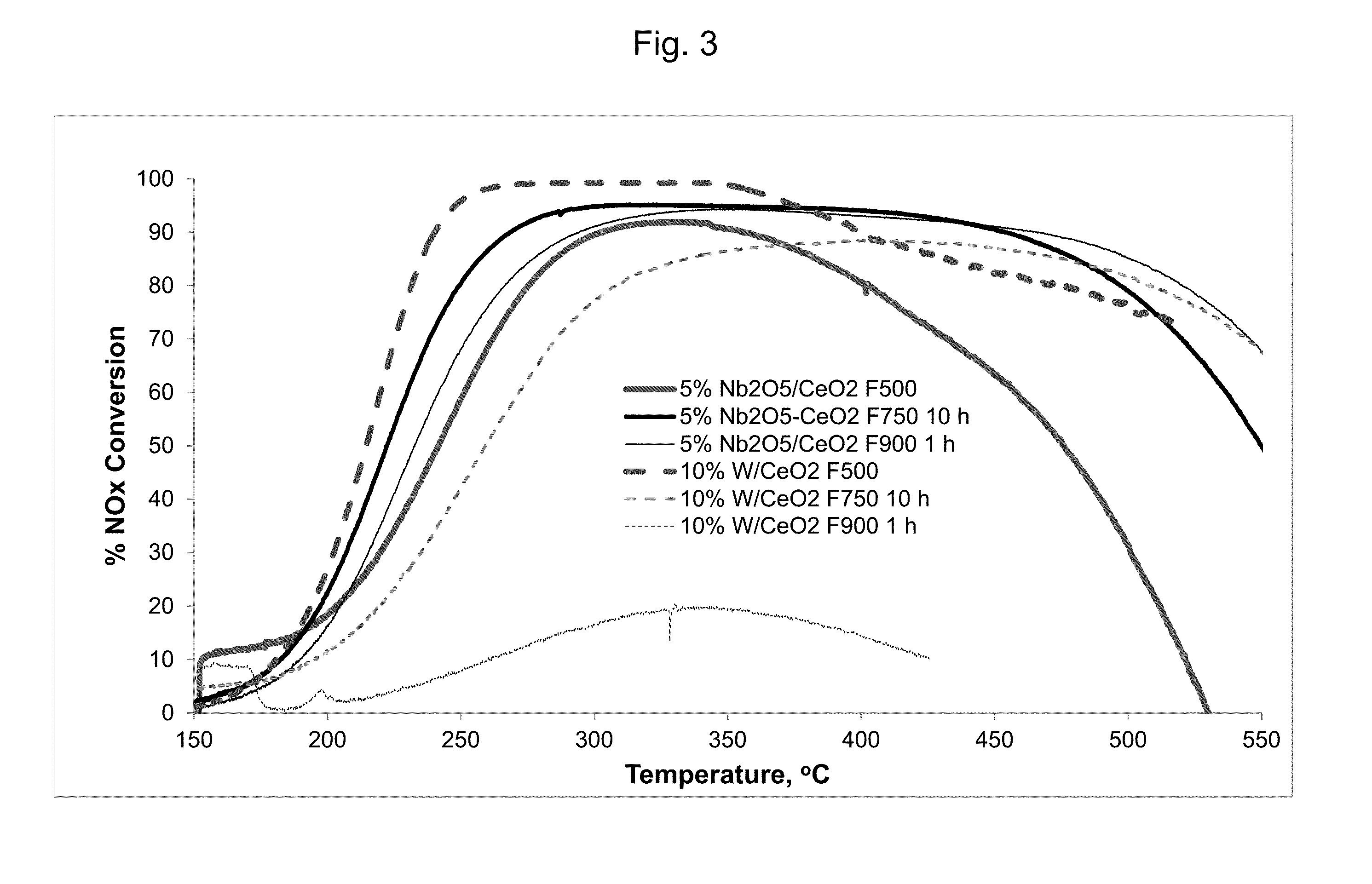
[0089]Ammonium niobate(V) oxalate (21% Nb, 1.06 g, 2.4 mmol Nb, equivalent to 0.32 g Nb2O5) is dissolved in water (6 mL) with stirring and gentle warming. High-surface-area ceria (9.68 g) is added, and the mixture is stirred. The pore volume of the ceria is slightly exceeded so the sample is stirred / warmed to dryness on a hotplate. The sample is further dried in an oven at 105° C. Portions of the sample are calcined (“fired”) at 500° C. for 2 h or at 800° C. for 4 h (10° C. / min ramp rate).

example 2

Preparation of Niobia-Doped Ceria (5.0 wt. % Nb2O5)

[0090]The procedure of Example 1 is generally followed using ammonium niobate(V) oxalate (3.33 g, 7.52 mmol Nb, equivalent to 1.0 g of Nb2O5), ceria (19 g), and water (12 mL).

example 3

Preparation of Niobia-Doped Ceria (8.6 wt. % Nb2O5)

[0091]The procedure of Example 1 is generally followed using ammonium niobate(V) oxalate (2.86 g, 6.47 mmol Nb, equivalent to 0.86 g of Nb2O5), ceria (9.14 g), and water (6 mL).

[0092]In Comparative Examples 4-6, the procedure of PCT Int. Publ. No. WO 2012 / 004263 (Rhodia) is generally followed to produce catalysts in which ceria is formed in the presence of niobia. Based on the preparation method, the catalysts should have a core of niobia surrounded by a ceria shell.


PUM

PropertyMeasurementUnit
temperatureaaaaaaaaaa
wt. %aaaaaaaaaa

Abstract

Niobia- and tantala-doped ceria catalysts, their use in selective catalytic reduction (SCR) processes, and a compact after-treatment system for exhaust gases are disclosed. In some aspects, the catalyst comprises at least 91 wt. % of ceria and 0.1 to 9 wt. % of niobia or tantala doped on the ceria. While conventional SCR catalysts can deactivate at higher temperatures, the doped cerias, particularly ones having as little as 1 or 2 wt. % of Nb2O5 or Ta2O5, are activated toward NOx conversion by calcination. The doped cerias are also valuable for SCRF® catalyzed filter applications, including an after-treatment system that comprises a diesel particulate filter having inlets and outlets, and a dual-function catalyst coated on the inlets, outlets, or both. Compared with conventional SCR catalysts, the niobia or tantala-doped cerias enable a higher level of NO2 to be present.

Description

FIELD OF THE INVENTION[0001]The invention relates to selective catalytic reduction processes utilizing ceria doped with low levels of niobia or tantala as a catalyst.BACKGROUND OF THE INVENTION[0002]Hydrocarbon combustion in diesel engines, stationary gas turbines, and other systems generates exhaust gas that must be treated to remove nitrogen oxides (NOx), including NO, NO2, and N2O. The exhaust generated in lean-burn engines is generally oxidative, and the NOx needs to be reduced selectively with a heterogeneous catalyst and a reductant, which is typically ammonia or a short-chain hydrocarbon. The process, known as selective catalytic reduction (SCR), has been thoroughly investigated.[0003]Various combinations of ceria and Group 5 metals (V, Nb, Ta) have been used for SCR and other catalytic processes. Usually, at least 10 wt. % of the Group 5 metal or Group 5 metal oxide is present in the catalyst, as is evident from a review of related academic publications.[0004]Le Gal et al. (...

Claims


Application Information

Patent Timeline
Patent Type & Authority Applications(United States)
IPC IPC(8): B01D53/94B01J23/20
CPCB01D53/9413B01D2255/207B01D2255/2065B01J23/20B01D53/9418B01D2251/2062B01D2255/9155B01D2258/012B01J37/0236B01J37/0244B01J37/0248B01J37/03B01J37/033B01J37/08B01J23/6484B01J23/6486B01J37/0201B01J37/0203B01J37/0211B01J2523/00Y02A50/20B01J35/19B01J35/30B01J35/615B01J2523/3712B01J2523/56B01J2523/57F01N3/035F01N3/2066B01J37/06B01D53/8628B01D53/945
Inventor FISHER, JANET MARYRAJARAM, RAJ RAOTHOMPSETT, DAVIDCOLLIER, JILLIAN ELAINE
Owner JOHNSON MATTHEY PLC
Learn More