Capacitive sensing and communicating

Inactive Publication Date: 2010-12-09
KONINKLIJKE PHILIPS ELECTRONICS NV
View PDF23 Cites 48 Cited by
  • Summary
  • Abstract
  • Description
  • Claims
  • Application Information

AI Technical Summary

Benefits of technology

[0030]In a second aspect of the present invention a system comprising a plurality of devices according to the first aspect is presented, wherein at least two devices of the plurality of devices are configured to communicate with each other. With a system of this kind, there is no need for using wires. Thus, no clutter of wires occurs. Further, the system is less complex as compared with a system employing an extra RF communication unit or other kind of communication unit. Hence, it can be low-power and low-cost. The system may potentially even be ultra low-power and low-cost, since it does not require an extra antenna and RF unit.
[0031]The system can be at least one of a body area network and a medical on-body sensor network. A system of such type may easily be employed e.g. for medical applications and does not need to be adapted so as to monitor a patient or serve other purposes.
[0032]In a third aspect of the present invention a device according to the first aspect is used for patient monitoring, sports performance coaching or wellness applications. When using the device for such applications, no wires or extra communication solutions are needed. Therefore, a more reliable, more convenient and cheaper setup is feasible.
[0033]In a fourth aspect of the present invention a method is presented that comprises: a) capacitively sensing a physiological signal from a human or animal body; and b) capacitively communicating a body coupled communication signal for a body area network, wherein the steps a) and b) are performed by a sensing unit of a device being placeable on or c

Problems solved by technology

Thus, when using BCC signals, a communication is only possible between devices situated on, connected to or placed close to the same human body.
This may result in many errors during operation of a system comprising a plurality of capacitive physiological sensing devices.
For example, when using such system in a clinical environment, errors may occur due to loose contacts and people moving.
Further, a system of this kind does not provide a convenient sensing for lifestyle applications such as e.g. wellness and sports, due to a clutter of wires.
In summary, sensing systems based on wired communications are unreliable

Method used


Image

  • Capacitive sensing and communicating
  • Capacitive sensing and communicating
  • Capacitive sensing and communicating

Examples


Embodiment Construction

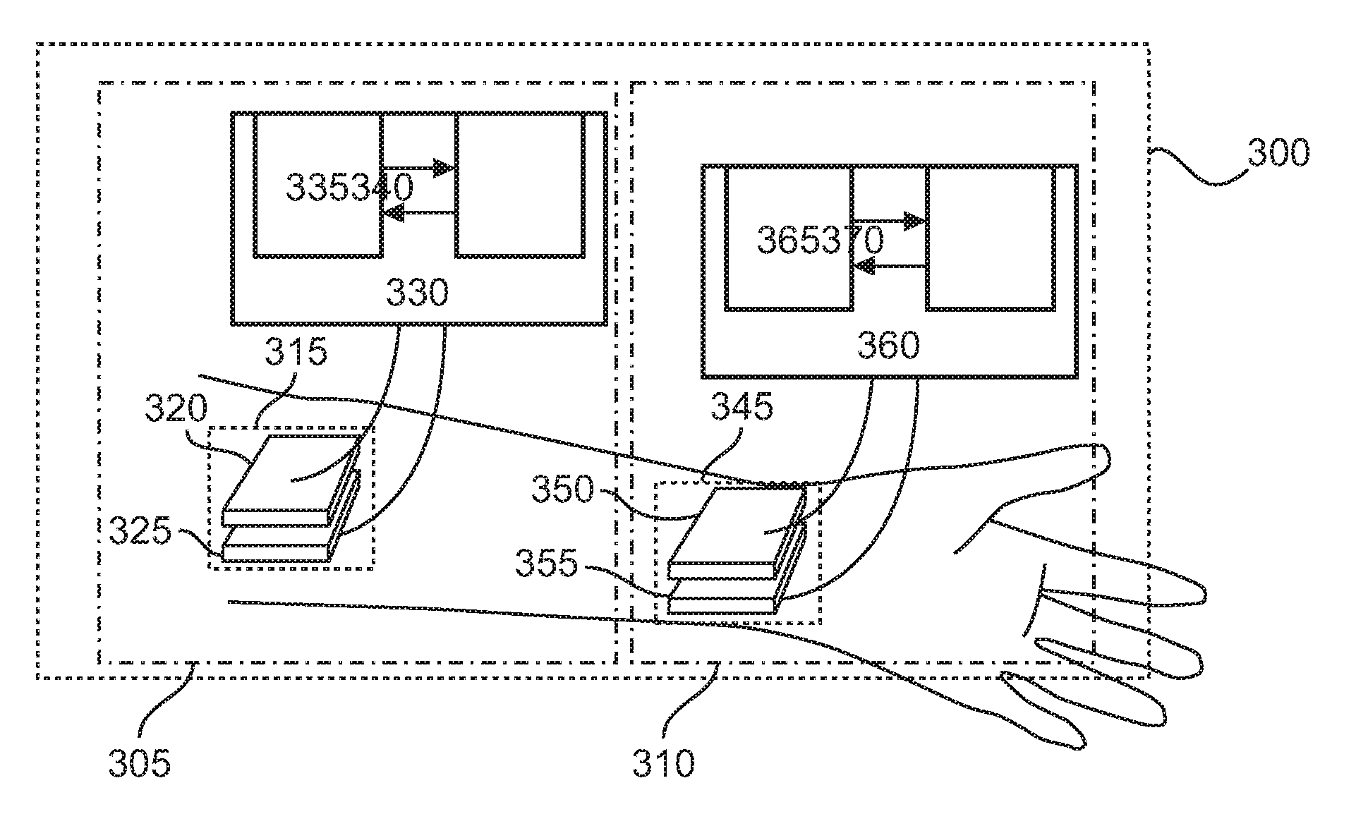
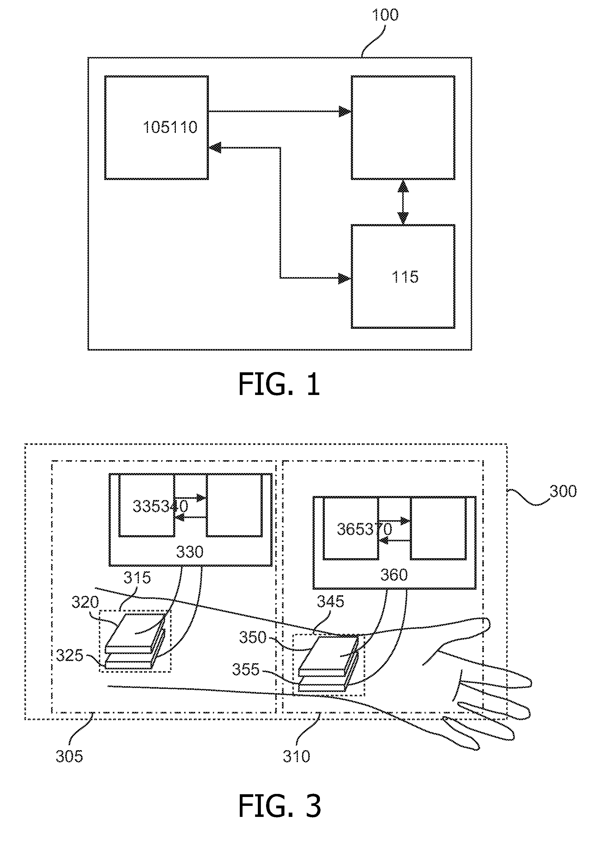
[0046]FIG. 1 shows a schematic block diagram illustrating the basic arrangement of an exemplary device according to the embodiment. A device 100 comprises a sensing portion or unit 105, a processing portion 110 and a transceiver portion 115. The device 100 can be a sensor or sensor node and is placeable on or close to a human or animal body. A physiological signal may be capacitively sensed or measured by the sensing unit 105. The sensed physiological signal may be supplied from the sensing unit 105 to the processing portion 110. The processing portion 110 can filter and process the sensed physiological signal. Further, it can store a processing result or the unprocessed physiological signal and supply the same to the transceiver portion 115. In addition, a body coupled communication (BCC) signal may be communicated by the sensing unit 105, wherein the human or animal body is used as a communication medium. The BCC signal can be intended for a body area network (BAN). The transceive...


PUM


Abstract

A device (100) which is placeable on or close to a human or animal body has at least a sensing unit (105) configured to capacitively sense a physiological signal from the human or animal body and capacitively communicate a body coupled communication signal. As sensing and body coupled communication capabilities can be provided by a single sensing unit, disadvantages of previous solutions for sensing and communicating like e.g. clutter of wires or increased costs and power consumption due to extra communication hardware can be alleviated.

Description

FIELD OF THE INVENTION[0001]The present invention generally relates to a device, a system, a method and a computer program for sensing a physiological signal and communicating a body coupled communication (BCC) signal.BACKGROUND OF THE INVENTION[0002]Body area networks (BANs) are a subset of wireless personal area networks (WPANs), which in turn are a subset of personal area networks (PANs). Such networks can be used for communicating data between devices that are located close to one person.[0003]BCC has been proposed as a prime candidate for the physical layer technology of BANs. It is also considered in the IEEE 802.15.6 BAN standardization.[0004]BCC signals are conveyed over a human body instead of through the air. Therefore, a communication based on such signals is confined to an area close to the human body. This is in contrast to radio frequency (RF) communications, where a much larger area is covered.[0005]Thus, when using BCC signals, a communication is only possible betwee...

Claims


Application Information

Patent Timeline
IPC IPC(8): A61B5/00G16H40/67
CPCA61B5/0006A61B5/0024H04B7/2671G06F19/3418H04W84/005H04W74/0891A61B5/6801A61B5/72A61B5/0002A61B5/0028A61B5/0402A61B5/0476A61B5/0488G06F19/3406H04B5/0012H04B13/005A61B2562/0214G16H40/63G16H40/67A61B5/318A61B5/389A61B5/369
Inventor SCHENK, TIM CORNEEL WILHELMUS
Owner KONINKLIJKE PHILIPS ELECTRONICS NV
Why Eureka
Try Eureka