Induction circuits for lighting

a technology of induction circuits and lighting, applied in the direction of electric variable regulation, water/sludge/sewage treatment, instruments, etc., can solve the problems of difficult to provide brightness control of fluorescent lamps, difficult to achieve brightness control of neon signs, and high capital cost of fluorescent lamp installation, etc., to achieve accurate measurement and low operating q

Inactive Publication Date: 2001-02-13
AUCKLAND UNISERVICES LTD
View PDF2 Cites 74 Cited by
  • Summary
  • Abstract
  • Description
  • Claims
  • Application Information

AI Technical Summary

Problems solved by technology

This ancillary circuitry results in a high capital cost for a fluorescent lamp installation and the starter device is at least as likely to fail during use as is the lamp itself.
Furthermore, it is difficult to provide brightness control of a fluorescent lamp.
Furthermore, brightness control of a neon sign is very difficult to achieve.
Another "wet" application is in illumination of spaces or in illuminated signs used outdoors, where contact by the public with a wet sign, perhaps in a case which has deteriorated, is likely to result in lethal shock.
Yet another application is in testing products for resistance to ultraviolet degradation where existing accelerated test methods prescribe a certain type, positioning, and number of lamps but at present cannot prescribe that they emit a controlled amount of light.

Method used


Image

  • Induction circuits for lighting
  • Induction circuits for lighting
  • Induction circuits for lighting

Examples


Embodiment Construction

PRINCIPLES

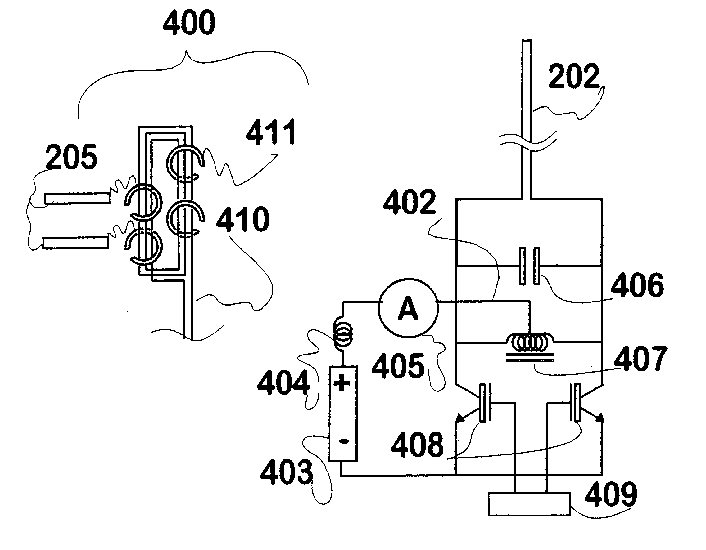
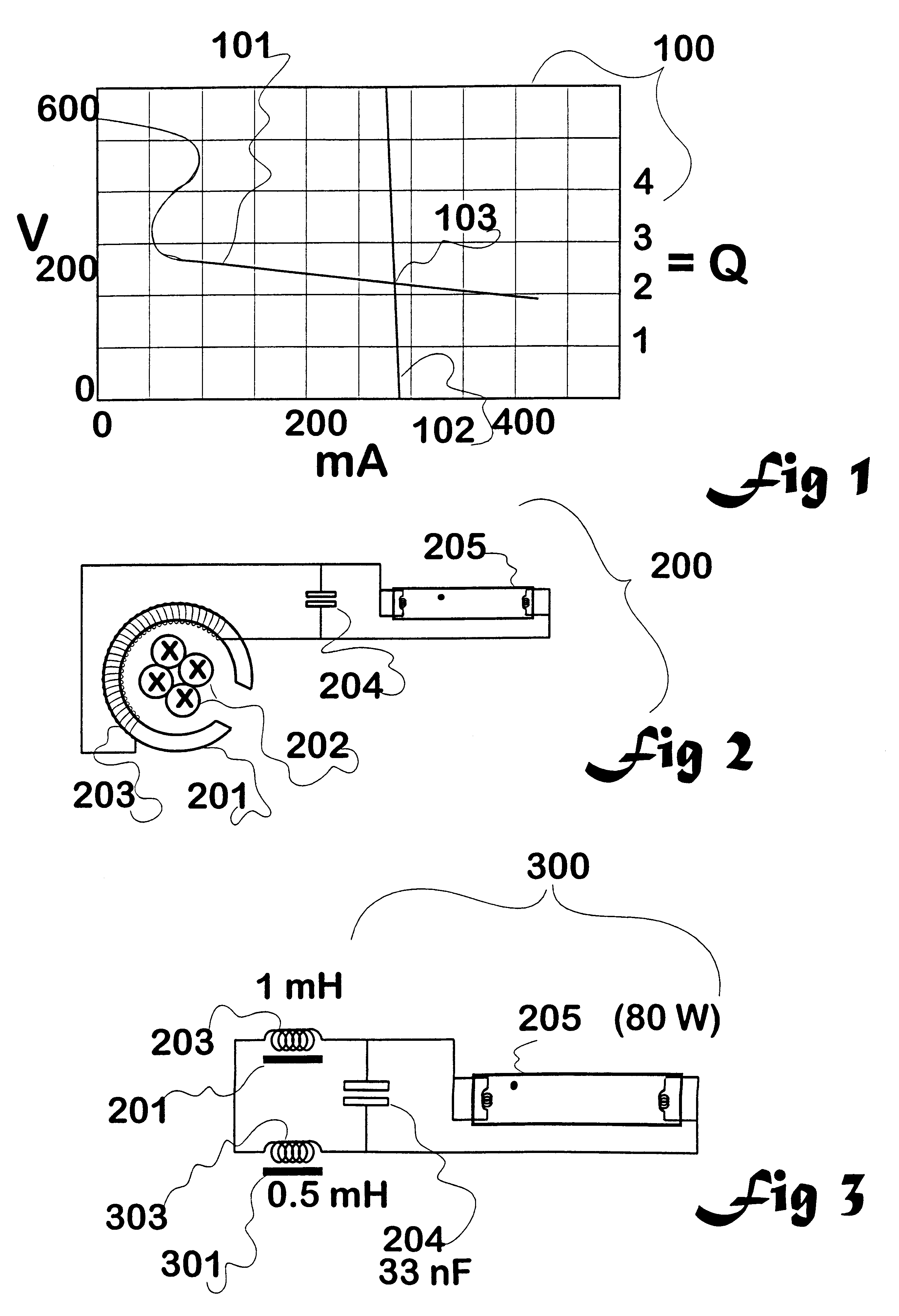
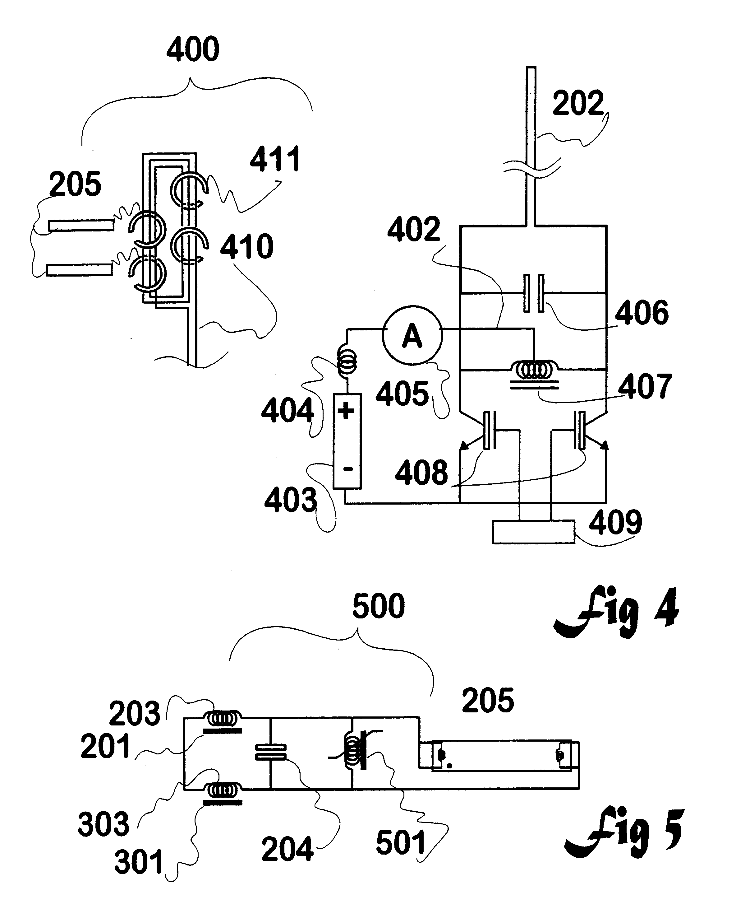
This invention relates to means to pick up current from a primary conductor carrying high-frequency, high-current electricity (such as 25 kHz, at 60 A) or optionally a multi-turn primary conductor having an equivalent amount of magnetic flux, and convert it into a form of power well suited to the characteristics of a gas-discharge lamp, which characteristics (see FIG. 1) are relatively difficult to satisfy.

The output of the invention powers a lamp with a current (proportional to a brightness) in proportion to the flux about the primary conductor, while the lamp current remains largely independent of the lamp's own "resistance" (assuming that the lamp is warm and that at least a minimum amount of power is supplied to it).

An example gas discharge lamp is a mercury vapour plus inert gas filled elongated glass tube of the type commonly referred to as a fluorescent lamp. This name refers to the use of one or more phosphors coating the inside of the glass tube, where they are ex...


PUM


Abstract

Disclosed is inductive coupling of power to devices having negative resistances, such as gas-filled discharge lamps (fluorescent tubes, neon signs, and the like) from a primary inductive loop, using resonant conditioning of the power provided to the device. A "C" shaped inductor (202) around the loop and a resonating capacitor (406) in parallel with the inductor provide a current source to the lamp (403) from across the capacitor. The circuit is capable of first igniting a lamp using a higher voltage available when the Q of the unloaded circuit is high, then running the lamp or other device at a controlled current. The lamp current is substantially proportional to the primary inductive loop flux, and substantially independent of the lamp resistance. A second inductor (404) in series with the first though not itself a collector of flux acts as a current limit. Applications include lighting, displays (optionally isolated and dimmable), and production of ultraviolet radiation.

Description

This invention relates to the field of inductive power transfer to negative-resistance devices such as gas-discharge and filament lamps, (including means to start the discharge) and in particular the invention relates to a resonant secondary circuit adapted to pick up power from an alternating magnetic field and provide power in a form matched to the requirements of a gas discharge lamp.An example gas discharge lamp is the type commonly referred to as a fluorescent lamp. This is generally a mercury vapour plus inert or rare gas (argon or a mixture of similar gases) at low pressure, sealed into an elongated glass tube that is provided with electrodes at each end. As the name suggests, visible light is emitted from fluorescing phosphors coating the inside of the glass tube when excited by ultraviolet light. A fluorescent lamp is normally driven from the AC mains (110 V, 60 Hz or 240 V, 50 Hz etc) and must be used in series with a ballast (to limit current; the lamp having a negative "...

Claims


Application Information

Patent Timeline
Patent Type & Authority Patents(United States)
IPC IPC(8): H05B41/282H05B41/28H05B41/24H05B41/392
CPCH05B41/24H05B41/2821C02F2201/32
Inventor BOYS, JOHN TALBOTGREEN, ANDREW WILLIAM
Owner AUCKLAND UNISERVICES LTD
Why Eureka
Try Eureka