Projection lens and projector using the same

a technology of projection lens and projector, which is applied in the field of projection lens, can solve the problems of large load for correction of distortion aberration and magnification chromatic aberration, non-uniform color and brightness, and inability to symmetrical principal rays

Inactive Publication Date: 2001-02-13
PANASONIC CORP
View PDF3 Cites 31 Cited by
  • Summary
  • Abstract
  • Description
  • Claims
  • Application Information

AI Technical Summary

Problems solved by technology

Therefore, the transmittance of a light ray that is incident at an angle other than a designated angle of incidence is changed, thus resulting in non-uniformity in color and brightness.
However, the following problem is caused.
This makes a large load for correction of the distortion aberration and the magnification chromatic aberration.
However, the principal ray cannot be symmetric, as long as telecentric properties are provided.
Therefore, the correction of the magnification chromatic aberration based on the F-line results in significant overcorrection for the g-line.
However, in a lens with telecentric properties or a wide angle lens, the magnification chromatic aberration is generated to a large extent.
In a projection lens for a projector that requires strict correction of the magnification chromatic aberration, even if the first-order magnification chromatic aberration has been corrected, the second-order magnification chromatic aberrations remains to a large extent, so that this causes problems for practical use.
As a result, a large magnification chromatic aberration is generated, and other aberrations are generated significantly.
Thus, the first-order magnification chromatic aberration has been corrected successfully, but it has been difficult to correct the second-order magnification chromatic aberration.
When the difference is below the lower limit, the correction is not successful due to the undercorrection of astigmatism.
When the difference is above the upper limit, the correction is not successful due to the overcorrection of astigmatism.
When the difference is below the lower limit, the correction is not successful due to the undercorrection of the first-order magnification chromatic aberration.
When the difference is below the lower limit, the correction is not successful due to the overcorrection of astigmatism.
When the difference is above the upper limit, the correction is not successful due to the undercorrection of the first-order magnification chromatic aberration.
When the difference is above the upper limit, the correction is not successful due to the undercorrection of the second-order magnification chromatic aberration.
When the ratio is below the lower limit, the correction is not successful due to the overcorrection of astigmatism.
When the ratio is above the upper limit, coma aberration or astigmatism cannot be corrected.

Method used


Image

  • Projection lens and projector using the same
  • Projection lens and projector using the same
  • Projection lens and projector using the same

Examples


example 1

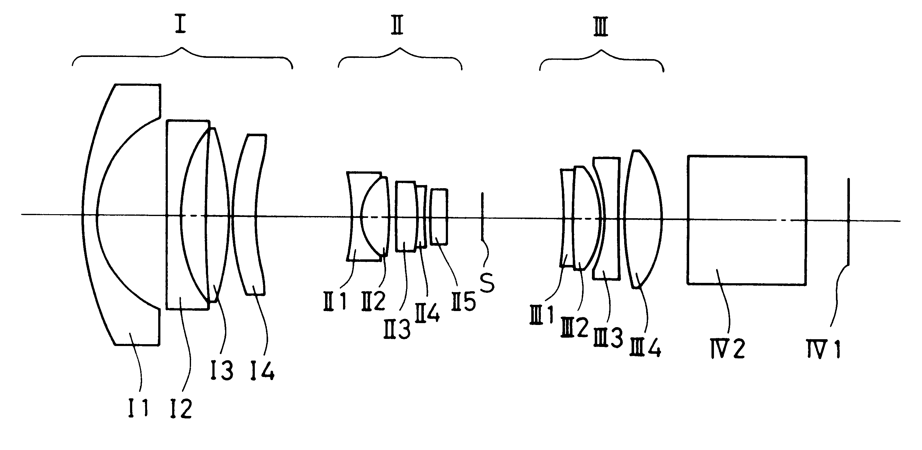
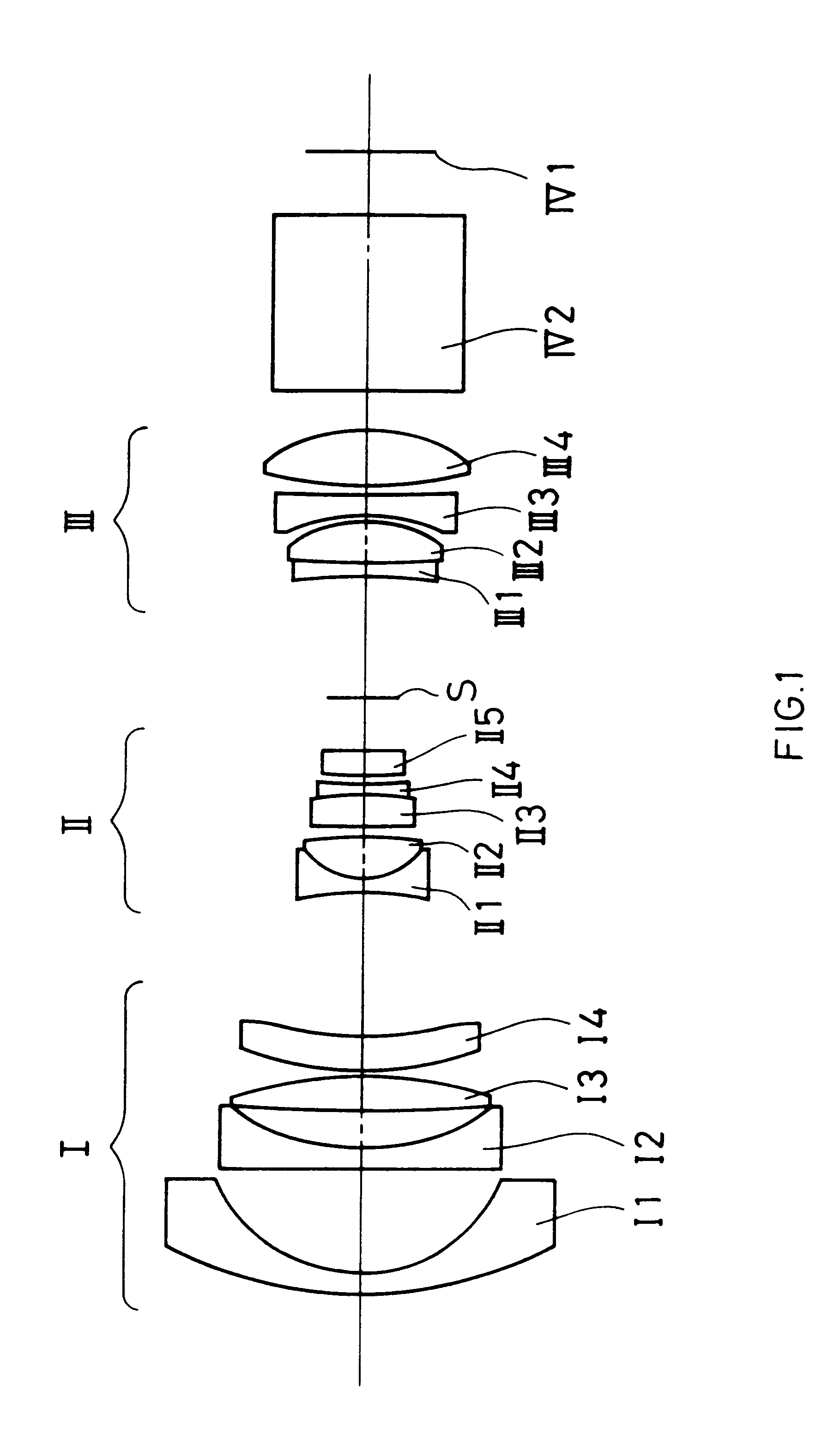
is a projection lens having F.sub.NO =3.0, a focal length f=10.52, and a half angle of view .omega.=44.degree.. This example is designed for the purpose of having a long back focal length and telecentric properties, and correcting the magnification chromatic aberration and the distortion aberration by satisfying the relationships (1) to (5).

Table 1 shows specific values. "ri" in Table 1 represents the radius of curvature of the surface of each lens, and the subscript "i" shows the number assigned to the surface of each lens sequentially from the screen. "di" represents the thickness of a lens or the gap between lenses, and the subscript "i" shows the number assigned to each lens or each gap between lenses sequentially from the screen. "ni" represents the refractive index on the d-line of each lens, and the subscript "i" shows the number assigned to each lens sequentially from the screen. "vi" represents the Abbe number on the d-line of each lens, and the subscript "i" shows the numb...

example 2

is a projection lens having F.sub.NO =3.0, a focal length f=10.40, and a half angle of view .omega.=44.degree.. This example is designed for the purpose of having a long back focal length and telecentric properties, and correcting the magnification chromatic aberration and the distortion aberration by satisfying the relationships (1) to (5).

Table 2 shows specific values. The symbols in Table 2 represent the same as those in Table 1 of Example 1.

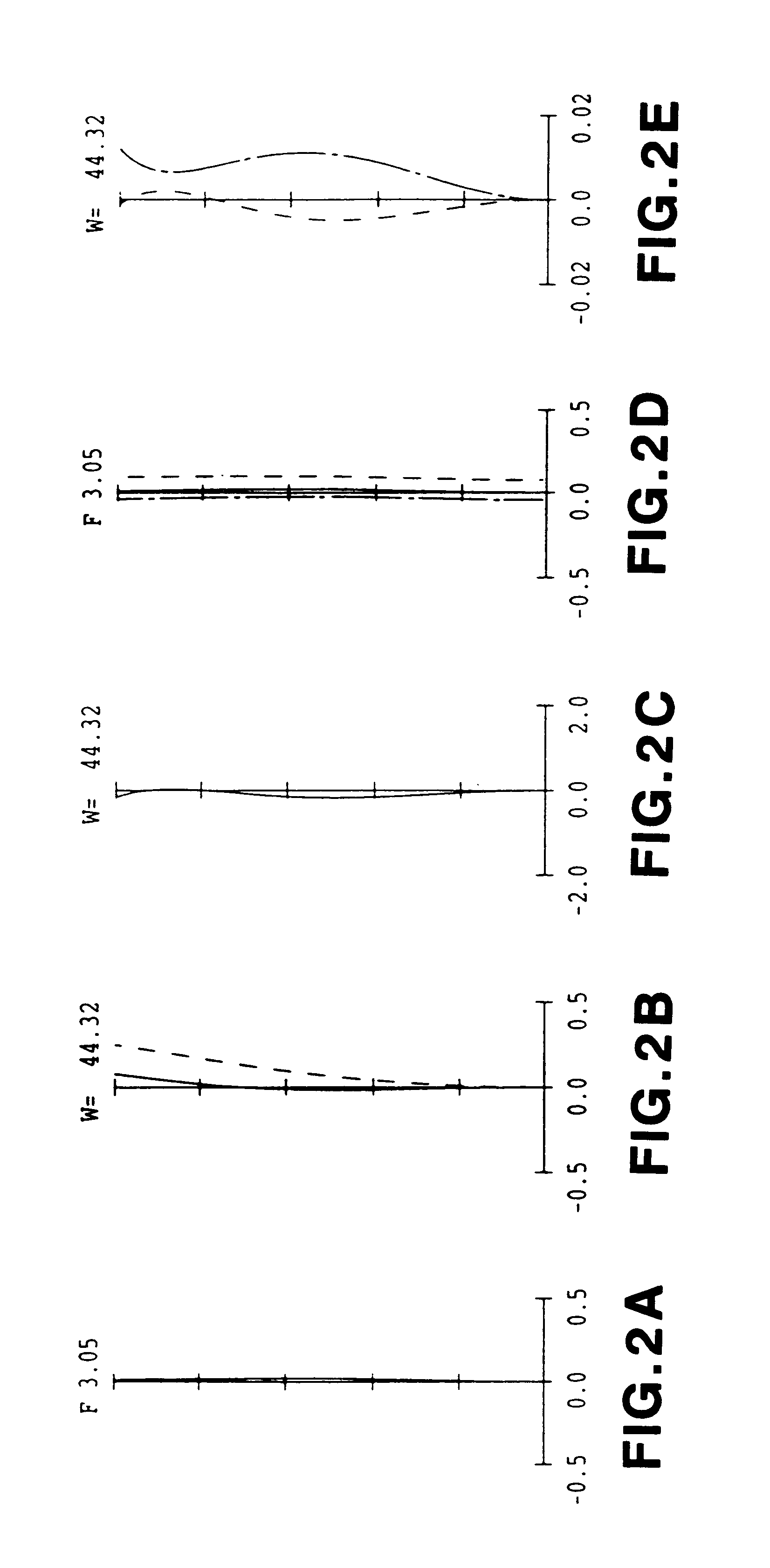
FIGS. 4 (a), (b), (c), (d) and (e) show the spherical aberration (mm), astigmatism (mm), distortion aberration (%), axial chromatic aberration (mm) and magnification chromatic aberration (mm) of Example 2, respectively. The graphs in FIG. 4 are plotted in the same manner as in FIG. 2.

Example 3

Hereinafter, Embodiment 1 will be described by Example 3 as another example with specific values.

FIG. 5 is a configuration diagram of the projection lens according to Example 3 of Embodiment 1. The components that have the same functions as those in FIG....

example 3

is a projection lens having F.sub.NO =3.0, a focal length f=10.42, and a half angle of view .omega.=44.degree.. This example is designed for the purpose of having a long back focal length and telecentric properties, and correcting the magnification chromatic aberration and the distortion aberration by satisfying the relationships (1) to (5).

Table 3 shows specific values. The symbols in Table 3 represent the same as those in Table 1 of Example 1.

FIGS. 6 (a), (b), (c), (d) and (e) show the spherical aberration (mm), astigmatism (mm), distortion aberration (%), axial chromatic aberration (mm) and magnification chromatic aberration (mm) of Example 3, respectively. The graphs in FIG. 6 are plotted in the same manner as in FIG. 2.

Example 4

Hereinafter, Embodiment 1 will be described by Example 4 as another example with specific values.

FIG. 7 is a configuration diagram of the projection lens according to Example 4 of Embodiment 1. The components that have the same functions as those in FIG....


PUM

PropertyMeasurementUnit
half angleaaaaaaaaaa
Abbe numberaaaaaaaaaa

Abstract

The present invention provides a projection lens for projecting light from a light source onto a screen to form a magnified image, including two joined lenses, each of which includes a negative lens and a positive lens. The difference in the refractive index and the Abbe number between the negative lens and the positive lens in each of the joined lenses and the partial dispersion ratio of the negative lens and the positive lens of the second joined lens are specified. Thus, a large angle of view and a long back focal length can be achieved while satisfying distortion aberrations, telecentric properties and magnification chromatic aberrations.

Description

1. Field of the InventionThe present invention relates to a projection lens, in particular, a projection lens for a projector that projects an image in a spatial optical modulator onto a screen in a larger size.2. Description of the Prior ArtThe following method conventionally is known to obtain large screen images. An optical image corresponding to an image signal is formed in a spatial optical modulator, and the optical image is irradiated with light so that the image is projected in a larger size onto a screen with a projection lens. Recently, a projector using a liquid crystal panel as the spatial optical modulator has been receiving attention. A projector using a reflection type liquid crystal panel as the spatial optical modulator can direct illumination light from a light source toward a projection lens more effectively.As a method for obtaining color images, the following methods are known: a method where three liquid crystal panels corresponding to image signals of R (red),...

Claims


Application Information

Patent Timeline
Patent Type & Authority Patents(United States)
IPC IPC(8): G02B13/22G02B13/16G02B13/04G02B13/24G02B13/18G02F1/13G02F1/1335G02F1/13357G03B21/00H04N5/74H04N9/31
CPCG02B13/16G02B13/22
Inventor KIMURA, SYUNSUKETAKAHASHI, MASAYUKI
Owner PANASONIC CORP
Why Eureka
Try Eureka