
Interplaced video signal encoding and decoding method, and encoding apparatus and decoding apparatus utilizing the method, providing high efficiency of encoding by conversion of periodically selected fields to progressive scan frames which function as reference frames for predictive encoding

a video signal and inter-frame prediction technology, applied in the direction of color television with bandwidth reduction, television systems, instruments, etc., can solve the problems of generating excessively large amounts of code in the predictive encoding process, unable to achieve a high efficiency of data compression through encoding, and inability to use a simple inter-frame prediction method to appropriate the purpose of picture encoding

Inactive Publication Date: 2001-02-13
RAKUTEN INC
View PDF11 Cites 150 Cited by
  • Summary
  • Abstract
  • Description
  • Claims
  • Application Information

AI Technical Summary

Benefits of technology

According to a second aspect, the invention provides a video decoding apparatus for executing decoding of successive code sequences which have been generated by encoding of progressive scanning frames derived by doubling the scanning line density of one in every m fields of an original interlaced video signal (where m is an integer of 2 or greater), with the encoding process using intra-frame predictive encoding or unidirectional predictive encoding, and by encoding remaining fields of said video signal directly as interlaced scanning fields, with the encoding process using bidrectional predictive encoding based on preceding and succeeding ones of said progressive scanning frames, the video decoding apparatus comprising:

Problems solved by technology

As a result, appropriate prediction for the purpose of picture encoding cannot be achieved by using a simple inter-frame prediction method.
As a result, even if the picture motion only consists of a parallel shift of the picture, comparatively large amounts of prediction error values will be generated and encoded, so that the predictive encoding process will generate excessively large amounts of code, i.e. the objective of achieving a high efficiency of data compression through encoding will not be met.
With a prior art type of interlaced video encoding apparatus, the problem arises that even if there is only a small amount of picture motion, it becomes impossible to perform accurate inter-picture prediction, due to the aliasing components which are contained in the interlaced picture signal.
As mentioned above, even if there is only a parallel shift of the picture, a substantial amount of inter-picture prediction error will be produced.
However since the total number of scanning lines of every picture would be doubled, the amount of encoding and decoding processing which must be executed would be correspondingly doubled, so that practical apparatus would be difficult.
A further problem which arises in the prior art is that when an interlaced video signal is obtained by reproduction from a recorded medium, or from a transmission source, the reconstructed interlaced pictures are not suitable for display by a progressive scanning type of monitor, such as is generally used to display text, images, etc., in the field of computers and data processing.

Method used


Image

  • Interplaced video signal encoding and decoding method, and encoding apparatus and decoding apparatus utilizing the method, providing high efficiency of encoding by conversion of periodically selected fields to progressive scan frames which function as reference frames for predictive encoding
  • Interplaced video signal encoding and decoding method, and encoding apparatus and decoding apparatus utilizing the method, providing high efficiency of encoding by conversion of periodically selected fields to progressive scan frames which function as reference frames for predictive encoding
  • Interplaced video signal encoding and decoding method, and encoding apparatus and decoding apparatus utilizing the method, providing high efficiency of encoding by conversion of periodically selected fields to progressive scan frames which function as reference frames for predictive encoding

Examples


Embodiment Construction

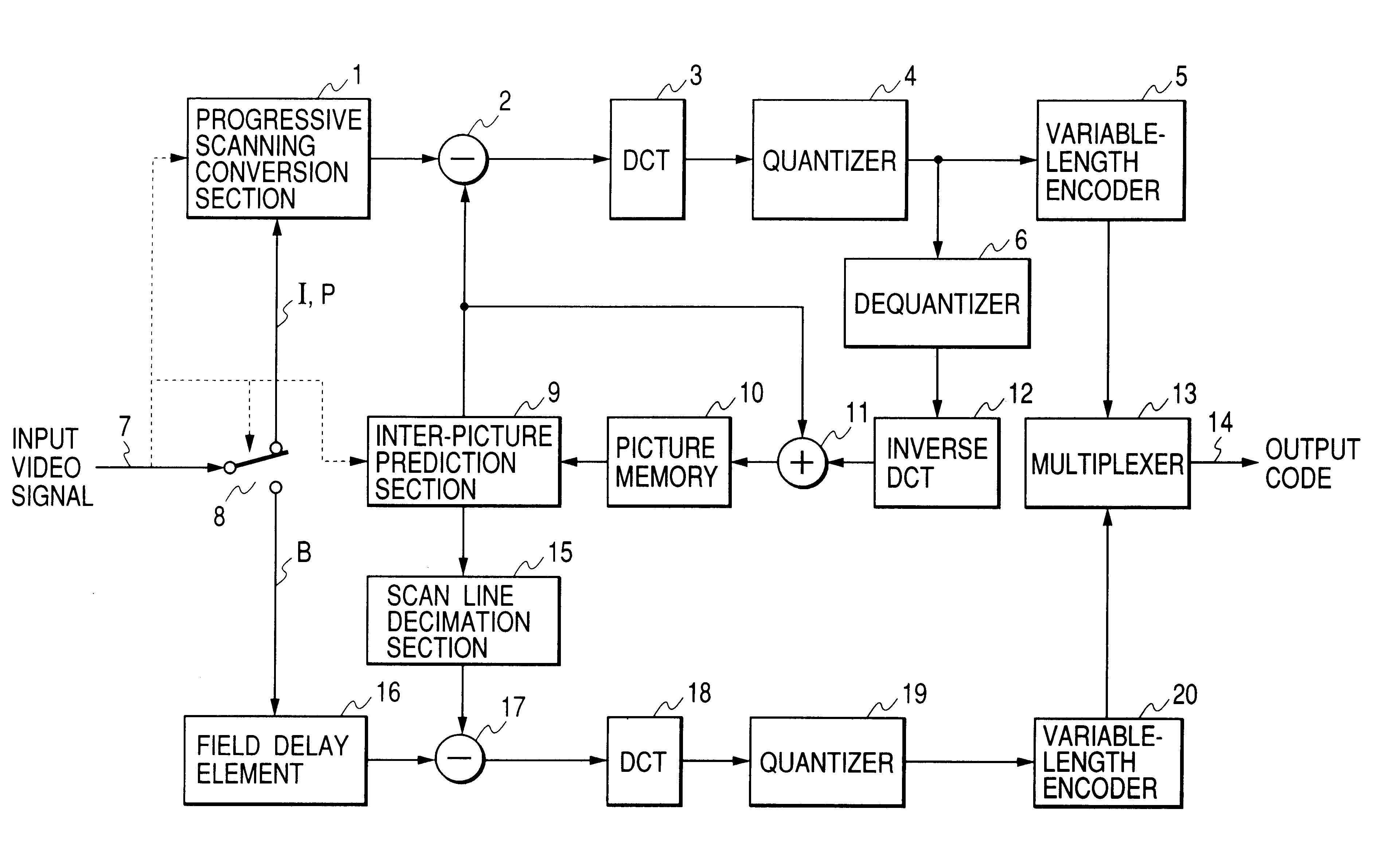
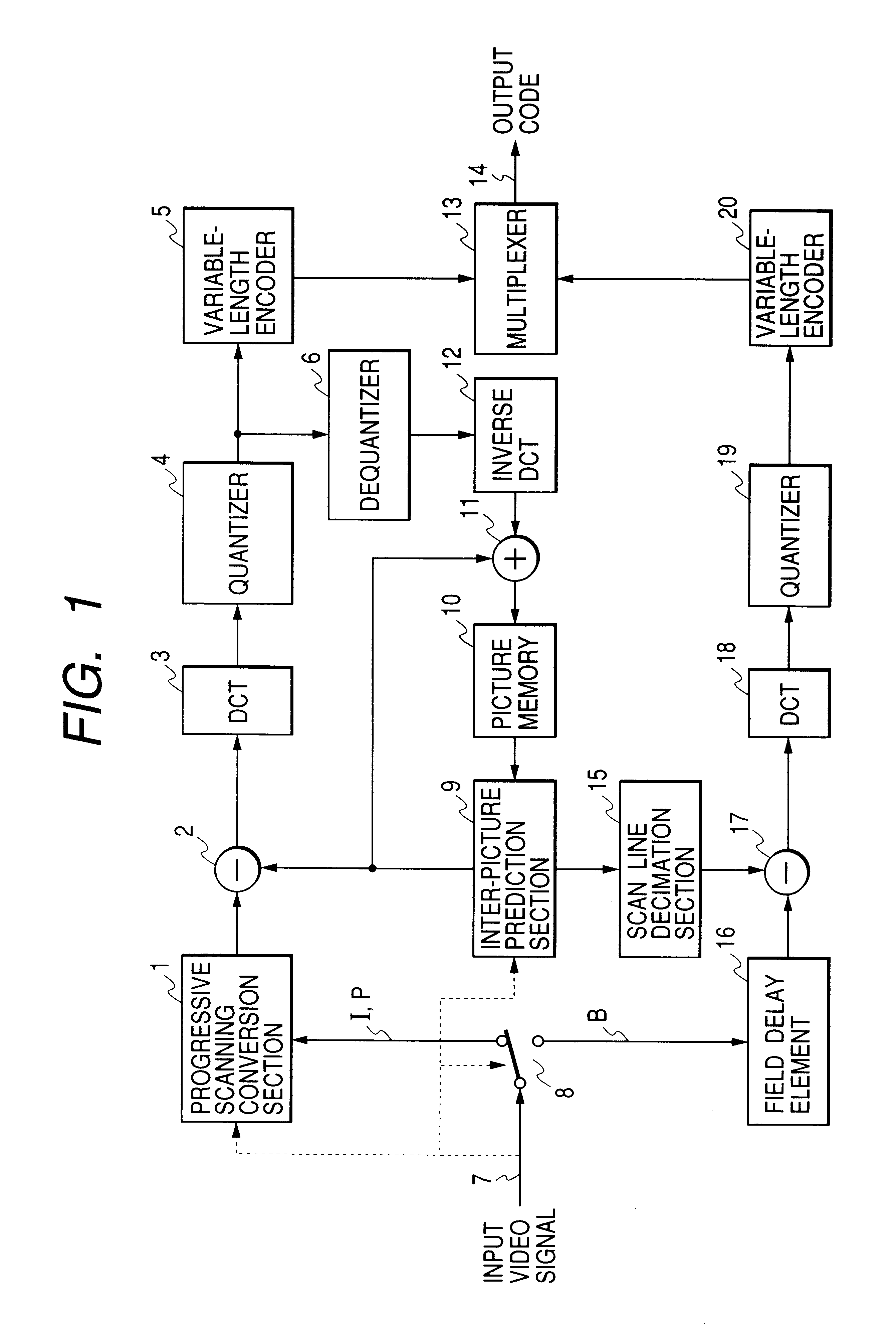
An embodiment of a motion-compensation encoding apparatus according to the present invention will be described in the following referring to the system block diagram of FIG. 1. In FIG. 1, elements that are identical in function and operation to elements of the prior art video encoding apparatus example of FIG. 5 are designated by identical numerals to those of FIG. 5. Basically, the apparatus of FIG. 1 differs from that of FIG. 5 by including a progressive scanning conversion section 1 and scanning line decimation section 15. Also, the frame delay element 61 of the prior art apparatus of FIG. 5 is changed to a field delay element 16, and the operation of the input signal selection switch 8 and of the inter-picture prediction section 9 respectively differ from those of the input signal selection switch 56 and inter-picture prediction section 57 of the prior art video encoding apparatus example of FIG. 5.

The processing executed with this embodiment will be described by comparison with...


PUM


Abstract

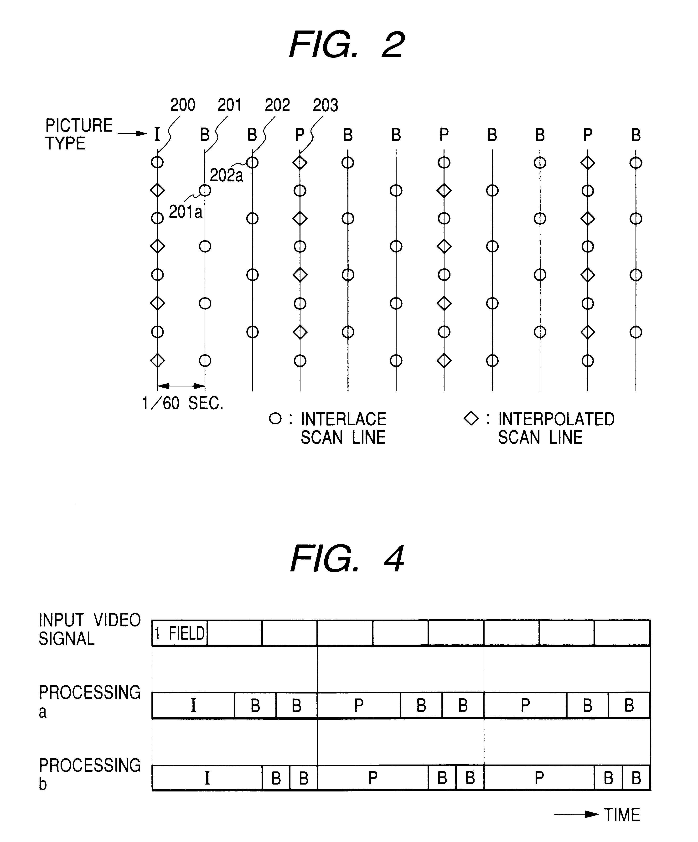
An encoding apparatus includes a selector for periodically selecting fields of an interlaced video signal to be converted to respective progressive scanning frames, by a scanning converter which doubles the number of scanning lines per field. The apparatus encodes these frames by intra-frame encoding or unidirectional predictive encoding using preceding ones of the frames, and encodes the remaining fields of the video signal by bidirectional prediction using preceding and succeeding ones of the progressive scanning frames for reference. The resultant code can be decoded by an inverse process to recover the interlaced video signal, or each decoded field can be converted to a progressive scanning frame to thereby enable output of a progressive scanning video signal. Enhanced accuracy of motion prediction for inter-frame encoding can thereby be achieved, and generation of encoded aliasing components suppressed, since all reference pictures are progressive scanning frames rather than pairs of fields constituting interlaced scanning frames.

Description

The present invention relates to a method and apparatus for high-efficiency encoding to efficiently convert an interlaced type of video signal into a stream of compressed code, for the purpose of transmission or storage. In particular, the invention relates to encoding processing which uses bidirectional motion prediction encoding, applied to an interlaced type of video signal.In the following, the term "picture" will be used as a general term for referring to the contents of afield of an interlaced video signal, or a frame of aprogressive scanning (i.e., non-interlaced) type of video signal.DESCRIPTION OF THE PRIOR ARTA method of high-efficiency video encoding for an interlaced type of video signal is known whereby one in every m successive frames (where m is an integer of 2 or more) is encoded either independently by internal encoding or by unidirectional predictive encoding, while the remaining frames (referred to as the B frames)are encoded by bidirectional predictive encoding u...

Claims


Application Information

Patent Timeline
Patent Type & Authority Patents(United States)
IPC IPC(8): G06T9/00H04N7/46H04N7/26H04N5/44H04N19/50H04N19/423H04N19/503H04N19/51H04N19/523H04N19/577H04N19/59H04N19/61H04N19/625H04N19/85H04N19/91
CPCH04N19/105H04N19/112H04N19/137H04N19/44H04N19/577H04N7/012H04N19/51
Inventor SUGIYAMA, KENJI
Owner RAKUTEN INC
Learn More