
Method and system for scaling, filtering, scan conversion, panoramic scaling, YC adjustment, and color conversion in a display controller

a display controller and scaling technology, applied in the field of video image processing, can solve the problems of consuming valuable resources, consuming memory, bandwidth, processing power, time, etc., and achieve the effect of reducing the size and power requirements of video manipulation hardware and reducing the number of computations performed

Inactive Publication Date: 2005-11-10
MICRONAS
View PDF17 Cites 23 Cited by
  • Summary
  • Abstract
  • Description
  • Claims
  • Application Information

AI Technical Summary

Benefits of technology

[0017] Various embodiments of the present invention provide a method of panoramic scaling that achieves a desired scaling ratio across an image by applying non-uniform scaling to generate one or more pixels in a panoramically scaled output line or column. For example, to achieve horizontal panoramic scaling, the method applies a horizontal scaling ratio similar to the vertical scaling ratio near the center of an output line and changes the scaling ratio used to generate pixels that are located successively further away from the center of the output line. To provide another example, the method linearly increases the scaling ratio used to generate pixels that are located successively further away from the center of the output line. Therefore, various embodiments of the present invention advantageously reduce visible distortion in a panoramically scaled image.
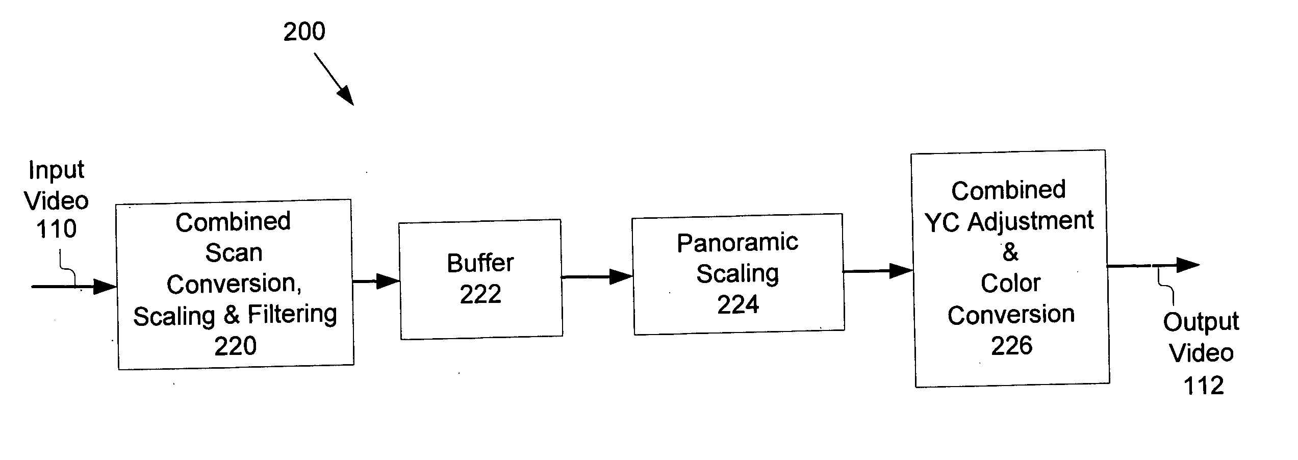
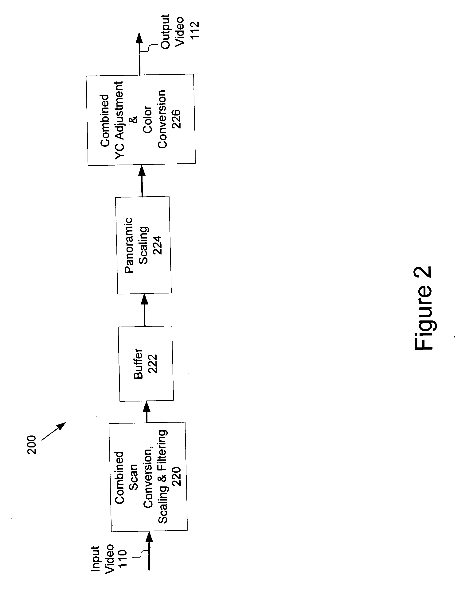
[0019] Various embodiments of the present invention provide a method of performing combined YC adjustment and color conversion of video data. The method first determines one or more combined coefficients for YC adjustment and color conversion. Next, the method applies the combined coefficient to the video data to achieve YC adjustment and color conversion in a single step. By combining YC adjustment and color conversion, one embodiment of the present invention advantageously reduces the size and power requirements of video manipulation hardware by reducing the number of logic gates and memory buffers required when YC adjustment and color conversion are implemented as separate operations.
[0020] According to one embodiment, at least one of the combined coefficients is a function of a YC adjustment parameter and / or a color conversion coefficient, and the value of the combined coefficient is determined by substituting a value of the YC adjustment parameter and / or the color conversion coefficient into a combined linear equation for YC adjustment and color conversion. According to a further embodiment, the step of determining the combined coefficients is performed prior to receiving the video data, thereby advantageously reducing the number of computations performed in real time. Various embodiments of the present invention provide a device for performing combined YC adjustment and color conversion.

Problems solved by technology

Processing of video data can be costly, consuming valuable resources such as memory, bandwidth, processing power, and time.
One problem with conventional video data processing is that panoramic scaling results in distortion of an image.
Panoramic scaling causes distortion because objects in the scaled frame appear elongated in the horizontal or vertical direction.
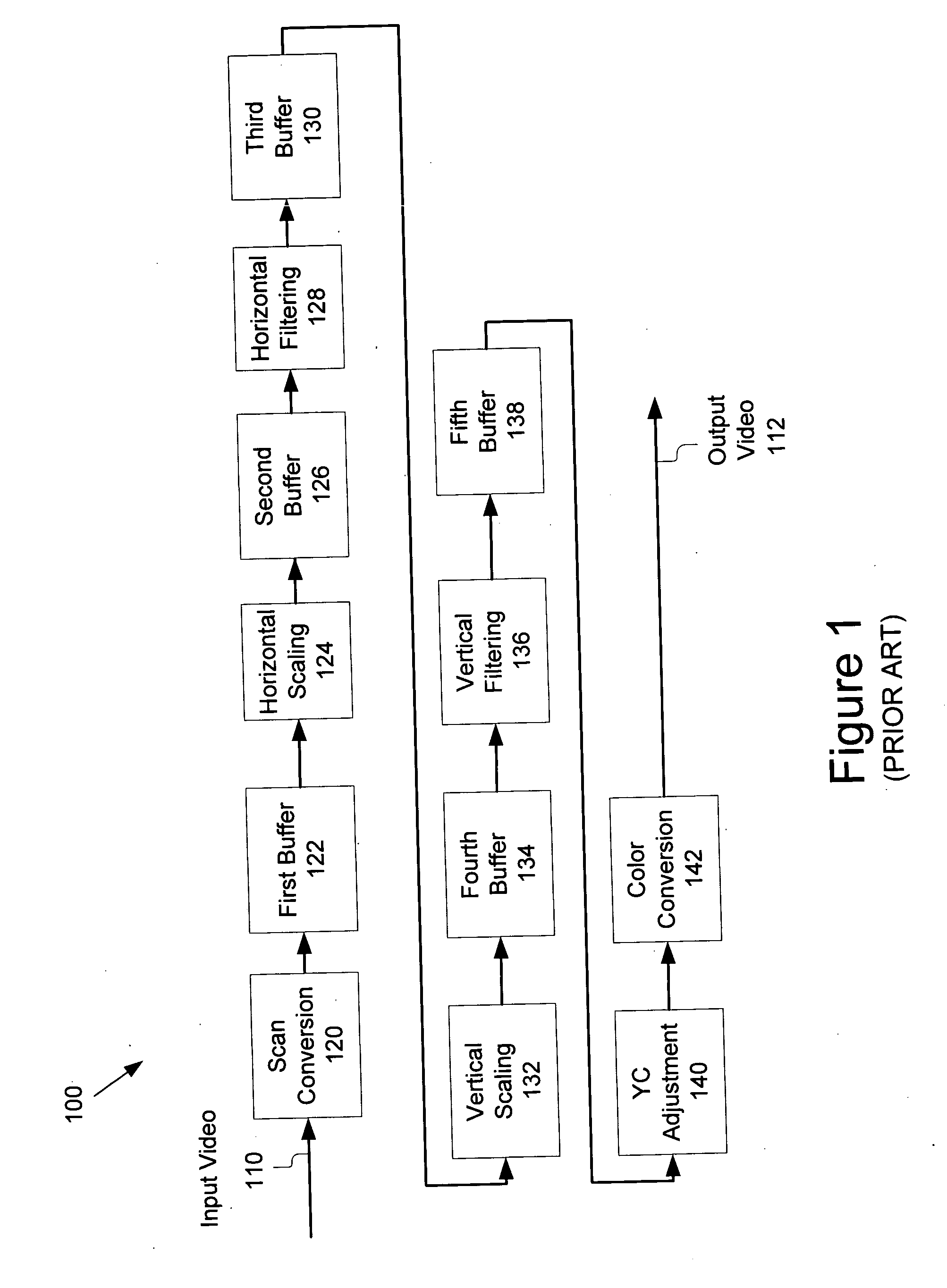
Another problem with conventional video data processing is delays introduced during separate operations of scaling, filtering, scan conversion, YC adjustment and color conversion.
Video processing that occurs at slower than video speeds requires large amounts of storage and cannot be viewed in real time.
These separate operations require large amounts of processing power, thereby introducing delays in video processing.
Further, these separate operations require numerous logic gates and large buffers, increasing both the chip size and power consumption.
This is particularly problematic for video processing system-on-chip (SOC) design, where small chip size and low power dissipation are highly desirable features.

Method used


Image

  • Method and system for scaling, filtering, scan conversion, panoramic scaling, YC adjustment, and color conversion in a display controller
  • Method and system for scaling, filtering, scan conversion, panoramic scaling, YC adjustment, and color conversion in a display controller
  • Method and system for scaling, filtering, scan conversion, panoramic scaling, YC adjustment, and color conversion in a display controller

Examples


Embodiment Construction

[0027] Various embodiments of present invention are now described more fully with reference to the accompanying figures, in which several embodiments of the invention are shown. The present invention may be embodied in many different forms and should not be construed as limited to the embodiments set forth herein. Rather these embodiments are provided so that this disclosure will be complete and will fully convey the invention to those skilled in the art.

[0028] In the following description, for purposes of explanation, numerous specific details are set forth in order to provide a thorough understanding of the invention. It will be apparent, however, to one skilled in the art that the invention can be practiced without these specific details. In some instances, structures and devices are shown in block diagram form in order to avoid obscuring the invention.

[0029] Reference in the specification to “one embodiment” or “an embodiment” means that a particular feature, structure, or cha...


PUM


Abstract

Techniques for performing panoramic scaling are disclosed that reduce visible distortion in a panoramic image. Further, techniques for performing combined YC adjustment and color conversion are disclosed that reduce the size and power requirements of video manipulation hardware by reducing the number of logic gates and memory buffers required when YC adjustment and color conversion are implemented as separate operations.

Description

CROSS-REFERENCE TO RELATED APPLICATION [0001] This application claims the benefit of U.S. Provisional Application No. 60 / 635,114, filed on Dec. 10, 2004. In addition, this application is a continuation-in-part of U.S. application Ser. No. 10 / 966,058, filed on Oct. 14, 2004, and titled “System and Method for Rapidly Scaling and Filtering Video Data”, which claims the benefit of 60 / 568,892, filed on May 7, 2004. In addition, this application is related to U.S. application Ser. No. ______ filed May 2, 2005, titled “Combined Scaling, Filtering and Scan Conversion”<attorney docket number 22682-09875>. Each of these applications is incorporated by reference herein in its entirety.BACKGROUND OF THE INVENTION [0002] 1. Field of the Invention [0003] The present invention relates generally to video image processing, and more particularly, to techniques for performing scaling, filtering, scan conversion, panoramic scaling, YC adjustment and color conversion on video data. [0004] 2. Backg...

Claims


Application Information

Patent Timeline
IPC IPC(8): G06F17/10G06T3/40G09G5/00G09G5/391H04N5/44H04N9/64H04N11/20
CPCG06T3/4007G06T3/4038G09G5/391G09G2340/0407H04N7/01H04N11/20H04N7/0125H04N9/64H04N9/641H04N9/67H04N9/68H04N7/0122
Inventor TIAN, YU T.HUANG, QIFANSHA, LI
Owner MICRONAS
Learn More