Apparatus and method for converting image data

a technology of image data and apparatus, applied in the field of apparatus and method for converting image data, can solve the problems of inability to process a smaller amount (bit rate) of image data than mpeg1 image data, mpeg2 image data encoding system cannot process image codes that are compressed at higher ratios, and it is difficult to provide an inexpensive apparatus. , to achieve the effect of low cos

Inactive Publication Date: 2006-08-08
SONY CORP
View PDF6 Cites 23 Cited by
  • Summary
  • Abstract
  • Description
  • Claims
  • Application Information

AI Technical Summary

Benefits of technology

[0067]The present invention has been made in consideration of the foregoing. The object of the invention is to provide an apparatus and method that can convert, at low cost and in real time, interlaced-scan MPEG2-image compressed data (bit stream) to sequential-scan MPEG4-image compressed data (bit stream).
[0074]According to the present invention, the first compressed image data is decoded by using only lower mth-order orthogonal transform coefficients included in nth-order orthogonal transform coefficients (where m<n), in both a vertical direction and a horizontal direction in the first compressed image data. Then, interlaced-scan data is converted to serial-scan data. Further, the second compressed image data is generated from the serial-scan data. Hence, interlaced-scan MPEG2-image compressed data (bit stream) can be converted to sequential-scan MPEG4-image compressed data (bit stream) at low cost and in real time, by processing a small amount of data and using a video memory of small storage capacity.

Problems solved by technology

The MPEG2 data-encoding system described above can process high-quality image codes that are suitable for broadcasting, but cannot process a smaller amount (bit rate) of image data than MPEG1 image data.
In other words, the MPEG2 data-encoding system cannot process image codes that are compressed at higher ratios.
Inevitably, it is difficult to provide an inexpensive apparatus if only dedicated LSIs are used.
In this case, the apparatus may fail to operate in real time.

Method used


Image

  • Apparatus and method for converting image data
  • Apparatus and method for converting image data
  • Apparatus and method for converting image data

Examples


Embodiment Construction

[0089]A preferred embodiment of the present invention will be described, with reference to the accompanying drawings.

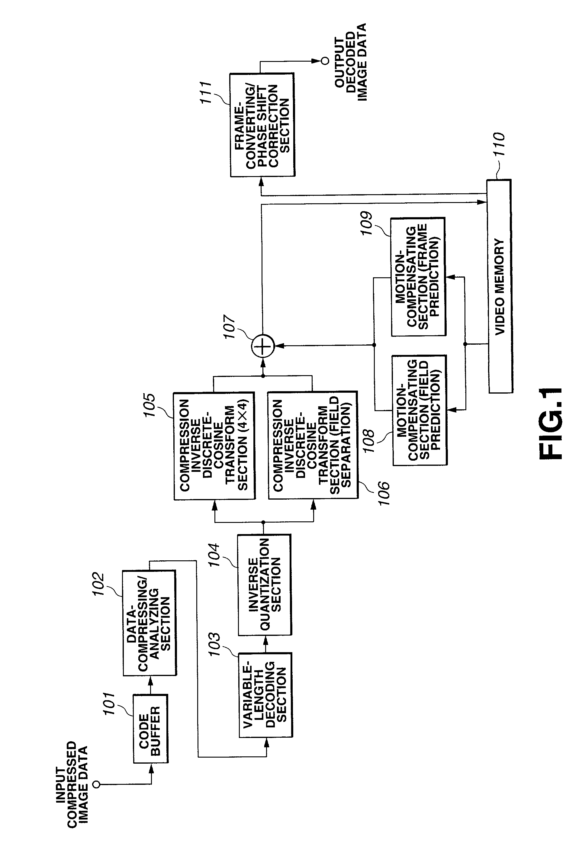
[0090]FIG. 12 is a schematic representation of an image data converting apparatus according to the invention.

[0091]As shown in FIG. 12, the frame data items contained in MPEG2-image compressed data (bit stream), i.e., interlaced-scan image data, is input the picture-type determining section 18.

[0092]The picture-type determining section 18 supplies the data about an I / P picture to the MPEG2-image data decoding section (i.e., I / P picture 4×8 down-decoder) 19, but discards the data about a B picture. Thus, the section 18 converts the frame rate.

[0093]The MPEG2-image data decoding section 19 performs the same process as does the apparatus shown in FIG. 1. However, the section 19 only needs to decode the I / P picture. This is because the picture-type determining section 18 already discarded the data about the B picture. The MPEG2-image data decoding section 19 only needs to...


PUM


Abstract

An image data converting apparatus comprising an MPEG2-image data decoding section 19, a scan-converting section 20, an MPEG4-image encoding section 21, and a picture-type determining section 18. The MPEG2-image data decoding section 19 decodes input MPEG2-image compressed data in both the vertical direction and the horizontal direction by using only lower, fourth-order coefficients. The scan-converting section 20 converts interlaced-scan pixel data to sequential-scan pixel data. The MPEG4-image encoding section 21 generates MPEG4-image compressed data from the sequential-scan pixel signals. The sections 19, 20 and 21 are connected in series. The picture-type determining section 18 is connected to the input of the MPEG2-image data decoding section 19. The section 18 determines the picture type of each frame data contained in the interlaced-scan MPEG4-picture compressed data, outputs only the frame data about I / P pictures, discards the frame data about B pictures, thereby converting the frame rate.

Description

CROSS-REFERENCE TO RELATED APPLICATIONS[0001]This application claims priority from Japanese Application No. 2000-017828 filed Jan. 21, 2000.BACKGROUND OF THE INVENTION[0002]The present invention relates to an apparatus and method for converting image data. The apparatus and the method are suitable in receiving compressed image data (i.e., bit streams) through network media (e.g., satellite broadcast, cable television and the Internet). The image data may be one that has been compressed by orthogonal transformation (e.g., discrete cosine transform) and motion compensation, as in an MPEG (Moving Picture image coding Experts Group) system. The apparatus and the method are suitable, too, in processing image data recorded on storage media such as optical disks and magnetic disks.[0003]In recent years, more and more apparatuses complying with the MPEG system are used in data-distributing facilities such as broadcast stations and data-receiving sites such as households. These apparatuses p...

Claims


Application Information

Patent Timeline
Patent Type & Authority Patents(United States)
IPC IPC(8): H04B1/66H04N19/50G06T9/00H03M7/30H04N19/114H04N19/132H04N19/159H04N19/172H04N19/40H04N19/423H04N19/426H04N19/51H04N19/587H04N19/59H04N19/60H04N19/625H04N19/80H04N19/85H04N19/91
CPCH04N5/4401H04N7/012H04N19/132H04N19/20H04N21/440281H04N19/40H04N19/577H04N21/440218H04N19/587H04N21/426
Inventor SATO, KAZUSHITAKAHASHI, KUNIAKIYIWEN, ZHUSUZUKI, TERUHIKOYAGASAKI, YOICHI
Owner SONY CORP
Why Eureka
Try Eureka