Switching power supply

Inactive Publication Date: 2001-02-20
NAGANO JAPAN RADIO CO LTD
View PDF5 Cites 35 Cited by
  • Summary
  • Abstract
  • Description
  • Claims
  • Application Information

AI Technical Summary

Benefits of technology

to provide a switching power supply which is capable of preventing abnormal operation of a synchronous rectifier circuit thereof, which is caused by a discont

Problems solved by technology

This can result in breakage of the FET 22 or an input fuse or a great deal of switching loss due to the large current flowing through the FET 22.
Therefore, when the power supply 71 has a large rated power, or when a plurality of power supplies 71 ar

Method used


Image

  • Switching power supply
  • Switching power supply
  • Switching power supply

Examples


Embodiment Construction

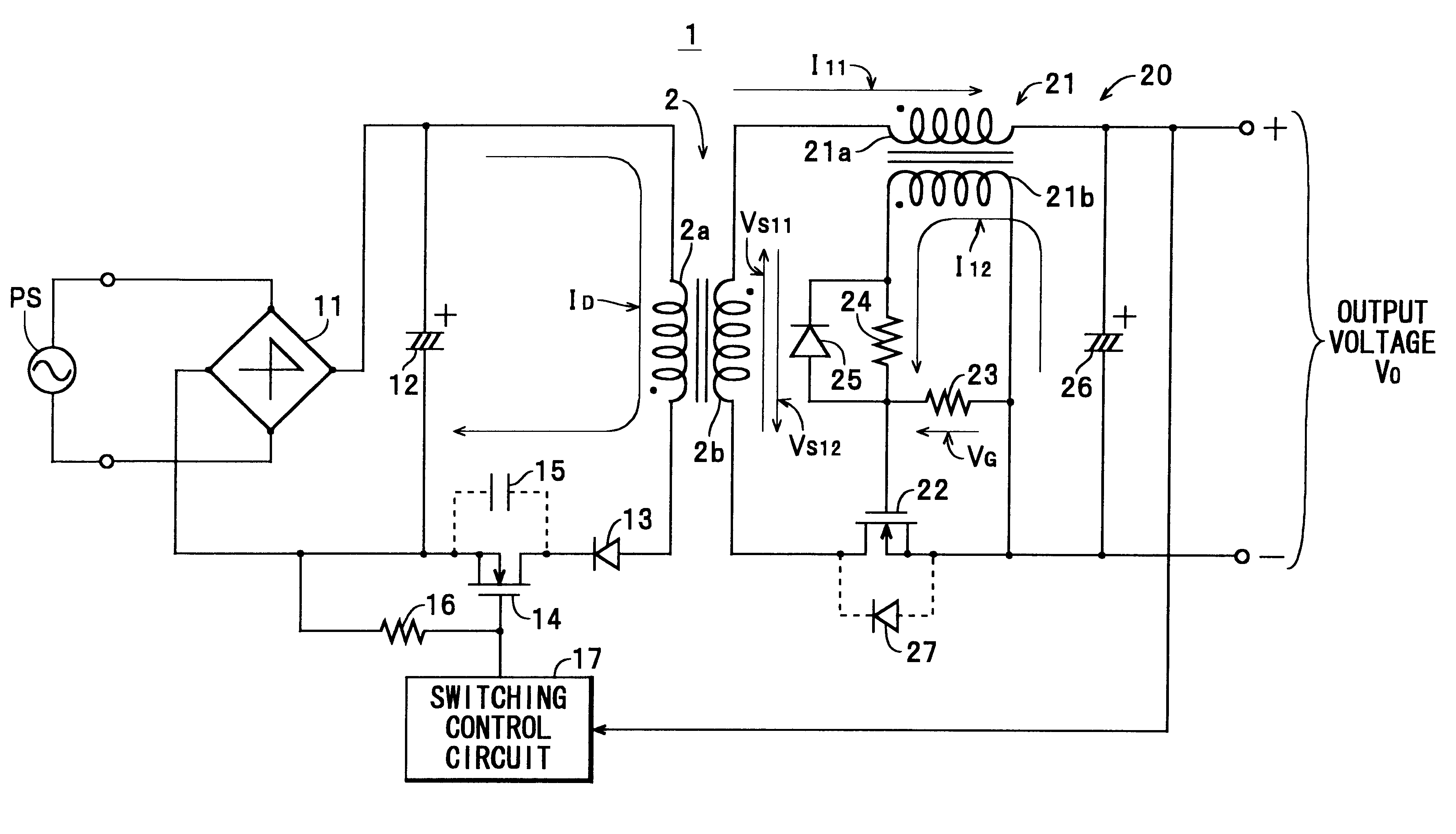
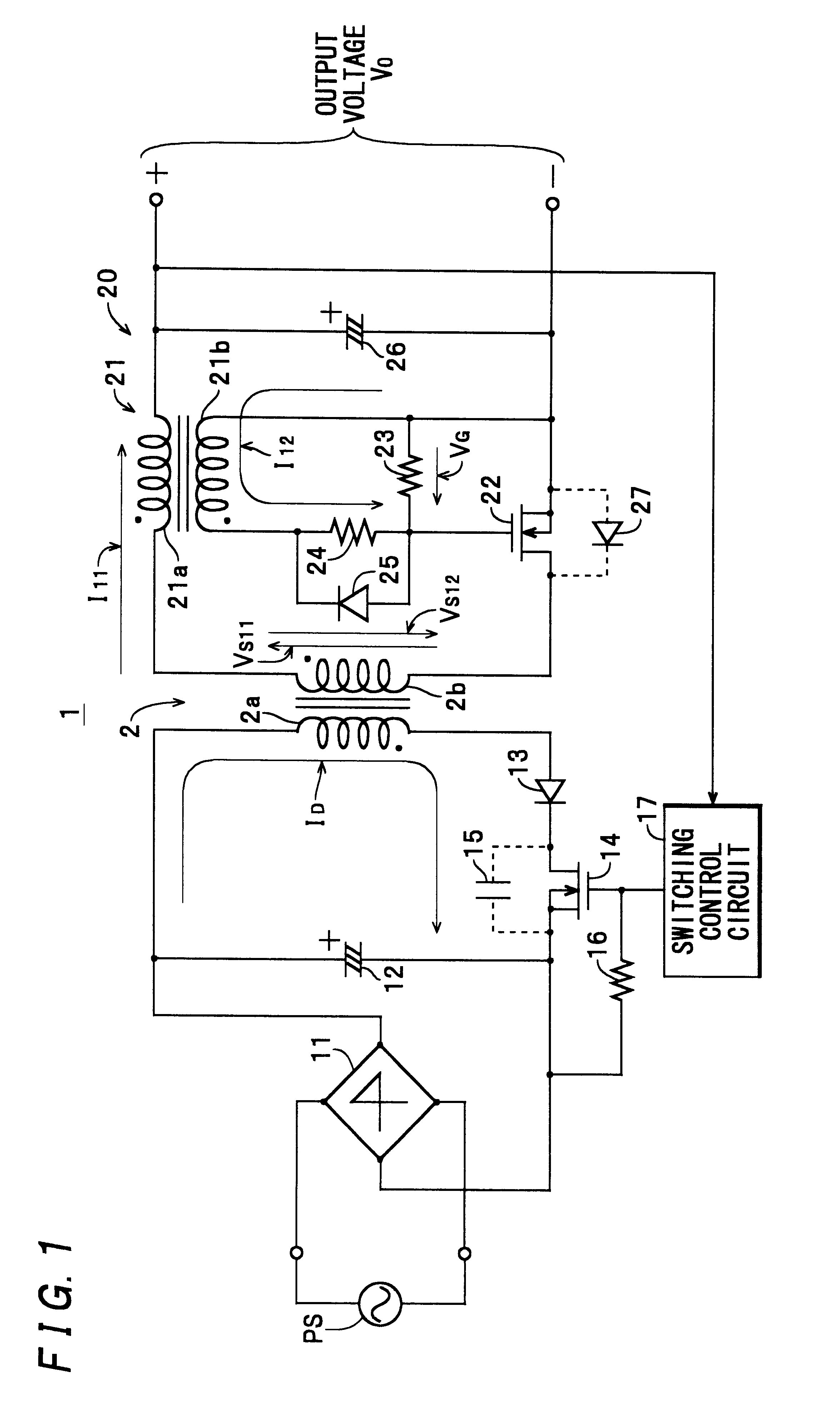
The invention will now be described in detail with reference to drawings showing embodiments thereof. In these embodiments, a switching power supply according to the invention is applied to a flyback-type switching power supply (hereinafter simply referred to as "the power supply"). In the following description of embodiments of the invention, component parts and elements similar to those of the power supply 71 of the related art described hereinbefore, as well as voltages and currents appearing at portions of the power supply corresponding to ones of the power supply 71 are designated by identical symbols, and detailed description thereof is omitted.

Referring first to FIG. 1, there is shown the power supply 1 including a primary circuit i.e. the primary winding-side circuit of a transformer 2, which is comprised of a diode stack 11 for rectifying an alternating current output from an AC power source PS, a smoothing capacitor 12, a diode 13 corresponding to current-limiting means of...


PUM


Abstract

A switching power supply is provided which is capable of preventing abnormal operation of a synchronous rectifier circuit thereof, which is caused by a discontinuous current mode, and capable of enhancing an input power factor thereof. A transformer has a primary winding and a secondary winding. A first switching element is connected in series with the primary winding of the transformer, for switching an input voltage. A diode rectifies an induced voltage induced in the secondary winding of the transformer to generate a rectified current. A control signal is generated which has a current value or a voltage value approximately proportional to a current value of the rectified current. A second switching element is connected in parallel with the diode in an equivalent fashion and has a control terminal to which the control signal is input. The second switching element operates in response to the control signal for rectifying the induced voltage. A current is prevented from flowing into the primary winding during an OFF period of the first switching element.

Description

1. Field of the InventionThis invention relates to a switching power supply of a synchronous rectification type for rectifying a voltage induced in a secondary winding of a switching transformer thereof in synchronism with induction of the voltage.2. Description of the Related ArtConventional switching power supplies usually employ the diode rectification method of rectifying and smoothing an alternating current output from a secondary winding of a switching transformer thereof by using a diode and a capacitor arranged on the side of the secondary winding. On the other hand, in recent years, a synchronous rectifier circuit using an FET as a rectifying element has been actively developed with a view to reducing power loss caused by the diode during the rectification. A power supply 71 shown in FIG. 8 is an example of the related art, i.e. the switching power supply having a synchronous rectifier circuit of the above-mentioned type.The power supply 71 is basically a flyback switching ...

Claims


Application Information

Patent Timeline
IPC IPC(8): H02M3/24H02M3/335H02M3/28
CPCH02M3/33592Y02B70/1475Y02B70/10
Inventor MATSUMOTO, AKIRA
Owner NAGANO JAPAN RADIO CO LTD
Why Eureka
Try Eureka