
Non-invasively maneuverable lead system

a lead system and non-invasive technology, applied in the field of non-invasively maneuverable lead systems, can solve the problems of difficult if not impossible to recruit the target nerve, trying to recruit specific nerve fibers without affecting other nerve fibers,

Inactive Publication Date: 2001-02-20
PLEXUS
View PDF5 Cites 123 Cited by
  • Summary
  • Abstract
  • Description
  • Claims
  • Application Information

AI Technical Summary

Benefits of technology

The Electrode Position Controller sends electromagnetic waves which are picked up and rectified into direct current pulses by the electronic circuit within the Lead Extension. These current pulses are applied to the micro-motor which causes its gear shaft to rotate just a few degrees per burst of electromagnetic waves. Since the Stimulating Lead is locked to the gear output shaft, the Stimulating Lead will also rotate when the micro-motor is energized. As the Stimulating Lead is rotated, the skew or spiral electrodes will slide perpendicularly to the target nerve, effectively changing, in very small and controlled steps, the position of the electrodes in relation to the target nerve.

Problems solved by technology

Trying to recruit specific nerve fibers without affecting other nerve fibers can be a very difficult and time consuming medical procedure.
Some types of neural stimulation are notoriously ineffective, such as lower back stimulation.
For some patients the physician may choose a lead having large spacing between electrodes in order to achieve complete paresthesia coverage, only to find out that such large spacing makes it too difficult if not impossible to recruit the target nerve.
A lead having closely spaced electrodes may facilitate recruitment of the target nerve but may not provide complete paresthesia coverage.
The main problem here is that manual pushing or pulling of the implanted lead by the physician often results in larger than desired changes in electrode position, making location of the "sweet spot" (parasthesia location) extremely difficult.
Furthermore, one of the major obstacles in preventing long term success of spinal cord stimulation for some patients, has been electrode displacement from their originally implanted position relative to the target nerve.
This results in a decreased or total loss of medical therapy.

Method used


Image

  • Non-invasively maneuverable lead system
  • Non-invasively maneuverable lead system
  • Non-invasively maneuverable lead system

Examples


Embodiment Construction

)

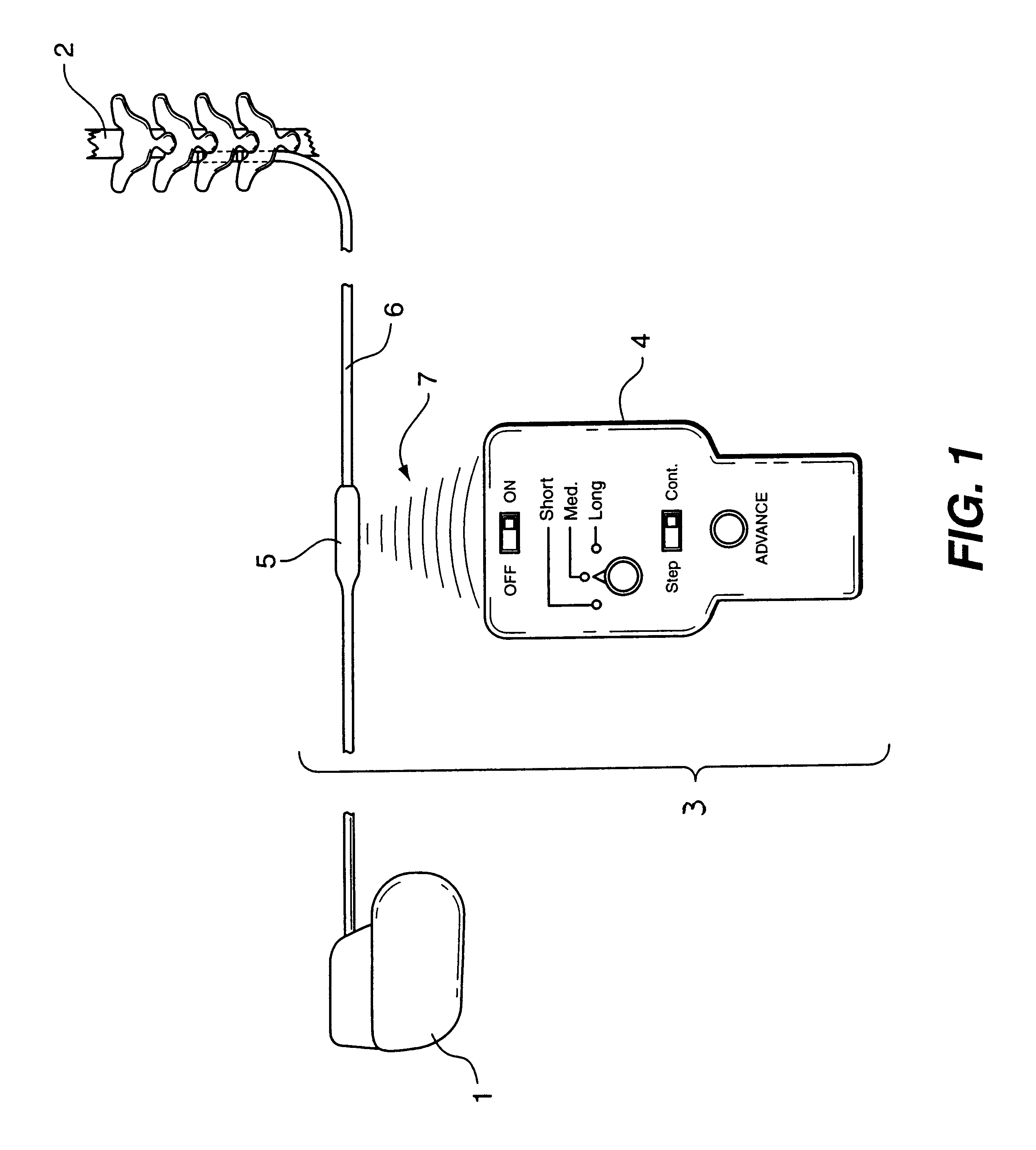
In FIG. 1 there is illustrated a block diagram of a non-invasively maneuverable lead system 3 constructed according to the teachings of the present invention and connected between an implanted pulse generator 1 and a spinal cord 2.

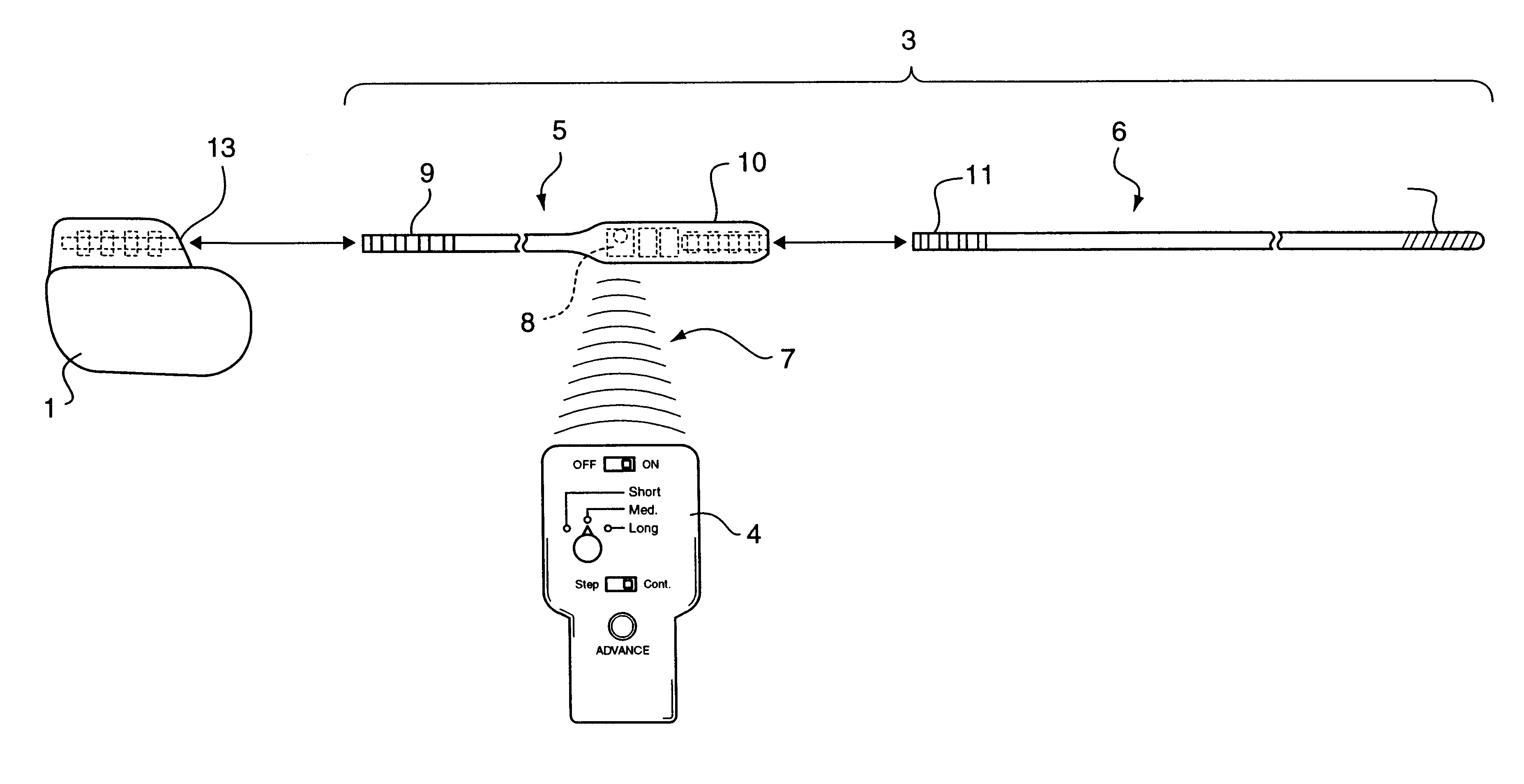
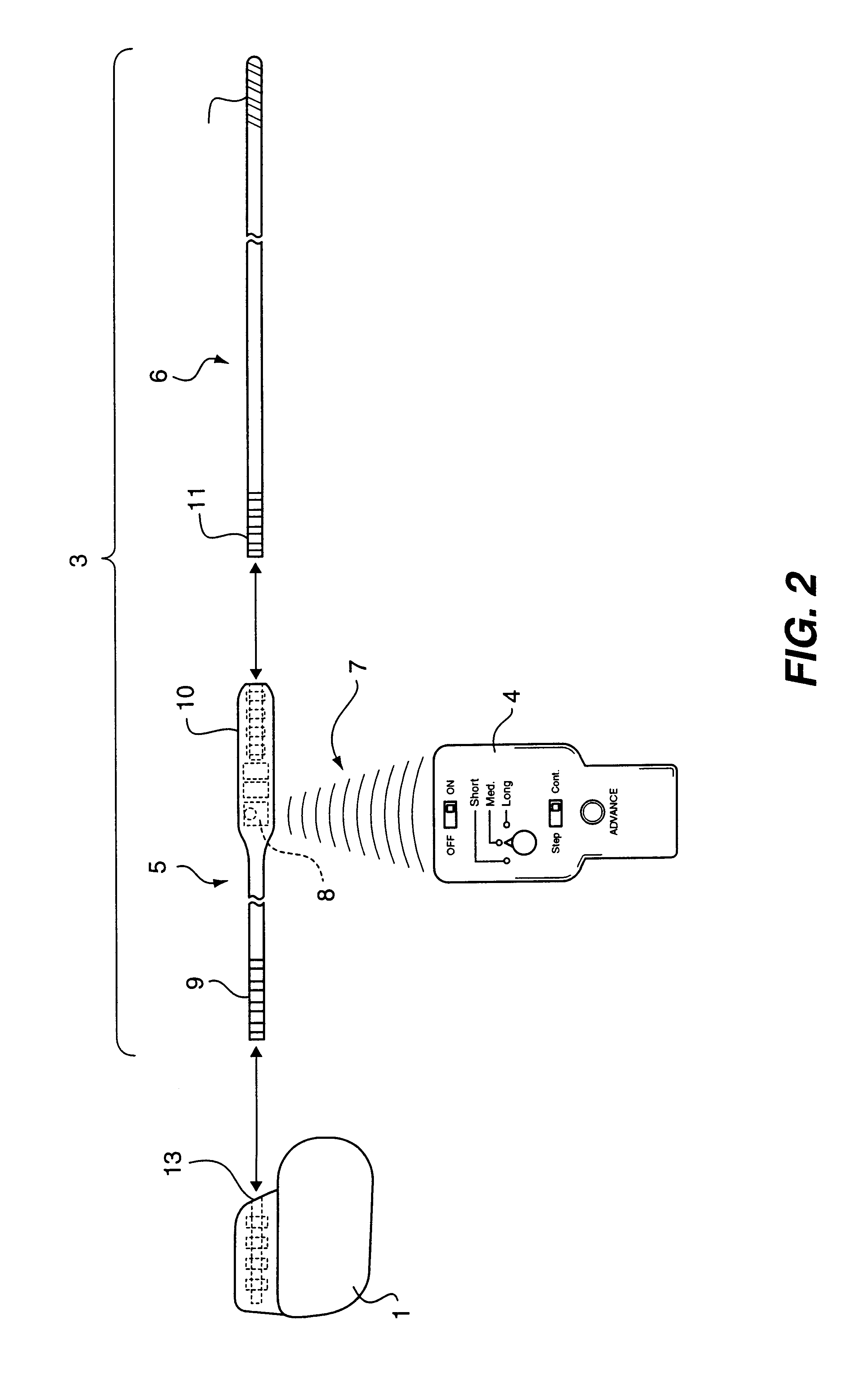
An electrode position controller 4 of the system 3 is used by a physician or medical technician to cause non-invasive, longitudinal micro-steps in lead position within the epidural space proximal to the spinal cord 2. This is accomplished by transmitting electromagnetic waves (drive signals) from the electrode position controller 4 to the lead extension 5 which causes small, controlled changes in electrode position of a stimulating lead 6 relative to the stationary target nerve.

In FIG. 2 there is shown an exploded view of the non-invasively maneuverable lead system 3. It shows how an implanted pulse generator 1, the lead extension 5 and the stimulating lead 6 are connected. It also shows the electrode position controller 4 transmitting electromagnetic wav...


PUM


Abstract

The method and system for non-invasively repositioning at least one stimulating electrode on a lead relative to tissue, such as nerve tissue, in a body includes elements for carrying out the method and the steps of: providing a lead having at least one stimulating electrode thereon which is located skew to an elongate axis of the lead; implanting the lead in a body; implanting in the body a drive mechanism having structure for engaging and rotating the lead; and, providing an exterior signal generating and transmitting mechanism for transmitting electromagnetic signals from outside the body to the drive mechanism implanted in the body for causing the drive mechanism to rotate the lead thereby to adjust the position of the at least one stimulating electrode on the lead relative to tissue in the body.

Description

1. Field of the InventionThe present invention relates to a method and system or apparatus for non-invasively adjusting the position of at least one implanted electrode.2. Description of the Prior ArtHeretofore, leads designed for electrical stimulation of human tissue generally comprise electrodes at their distal end which are connected to contacts at their proximal end via insulated conductor wires threaded inside a non-conductive sheath. In general, stimulation leads are used to transport electrical pulses from an implanted pulse generator to the target tissue.In the case of spinal cord stimulation, the target tissue is a secluded nerve fiber(s) within the spinal cord which transport a distinct neurological message to or from the brain. Two examples of a neurological message are (1) a signal to the brain intended to trigger a defensive or protective action, such as pain or (2) a signal from the brain intended to contract a specific muscle, such as the urinary bladder sphincter.In...

Claims


Application Information

Patent Timeline
Patent Type & Authority Patents(United States)
IPC IPC(8): A61N1/08A61N1/05
CPCA61N1/08A61N1/0551A61N1/36128
Inventor BARRERAS, SR., FRANCISCO JOSEJIMENEZ, OSCAR
Owner PLEXUS
Learn More