Automobile windshield molding and the method of producing the same

a technology for windshields and automobiles, applied in mechanical devices, roofs, transportation and packaging, etc., can solve the problems of deteriorating the decorativeness of molding, adversely affecting the external appearance of the upper molding, and difficult attachment of moldings to the windshield of automobiles, etc., to achieve sufficient retaining function, improve the drainage of rainwater, and improve the effect of rainwater drainag

Inactive Publication Date: 2001-03-06
TOKAI KOGYO CO LTD
View PDF90 Cites 16 Cited by
  • Summary
  • Abstract
  • Description
  • Claims
  • Application Information

AI Technical Summary

Benefits of technology

The above production method enables water drain channel to be provided only at the places where they are required, to change groove depth in the longitudinal direction to drain rainwater smoothly and to form the whole windshield molding as a single product.
Therefore, since the present invention is effective in providing water drain channel only at the places where they are required, in changing the water drain channel depth in the longitudinal direction to improve the drainage of rainwater and in forming the whole windshield molding as a single product by molding without adding other processes, it also enables the forming of windshield moldings with rainwater draining grooves of sufficient retaining function easily, satisfactorily and continuously.

Problems solved by technology

When they are coupled, there may be lines between joined areas of the molding parts, which would deteriorate the decorativeness of the molding.
The molding is difficult to attach in the windshield of the automobile since a portion of the molding is cut off to serve as a water drain channel.
Therefore, the decorative portion should be made large, which would adversely affect the external appearance of the upper molding, and reduce the field of view from the driver's position.
Such large upper molding part might be contrary to a demand for a flush surface between the windshield and the vehicle body panel.
Therefore, they cannot convey and drain rainwater effectively.
Windshield moldings with such grooves cannot be formed in one piece with current extrusion molding technology.
This requires larger injection molds and increased man hours, resulting in lower productivity.

Method used


Image

  • Automobile windshield molding and the method of producing the same
  • Automobile windshield molding and the method of producing the same
  • Automobile windshield molding and the method of producing the same

Examples


first embodiment

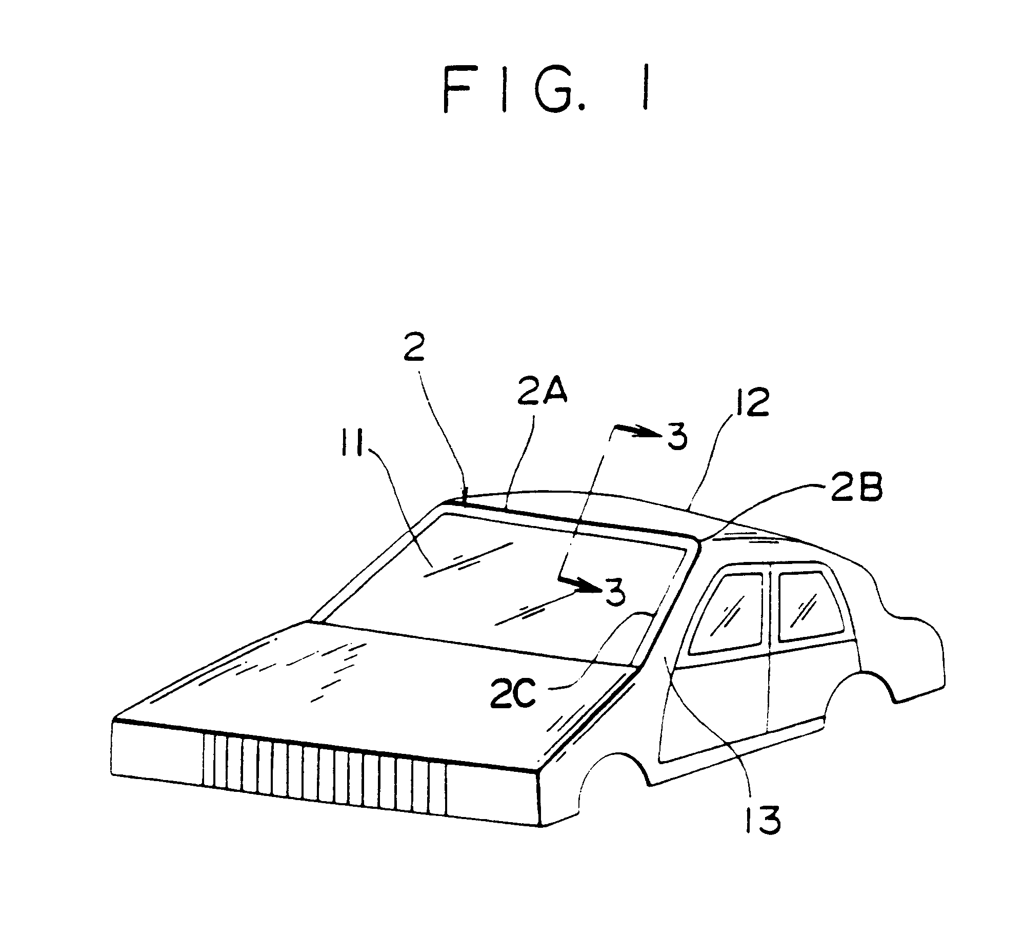
An automobile windshield molding according to the invention is shown in FIGS. 1 to 6.

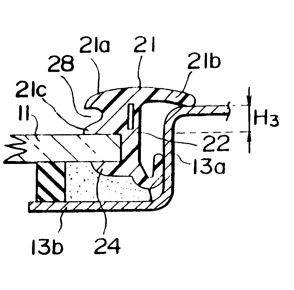
As shown in FIG. 1, a molding 2 is installed to seal the space between a windshield 11 and a periphery of a window opening of a vehicle body panel.

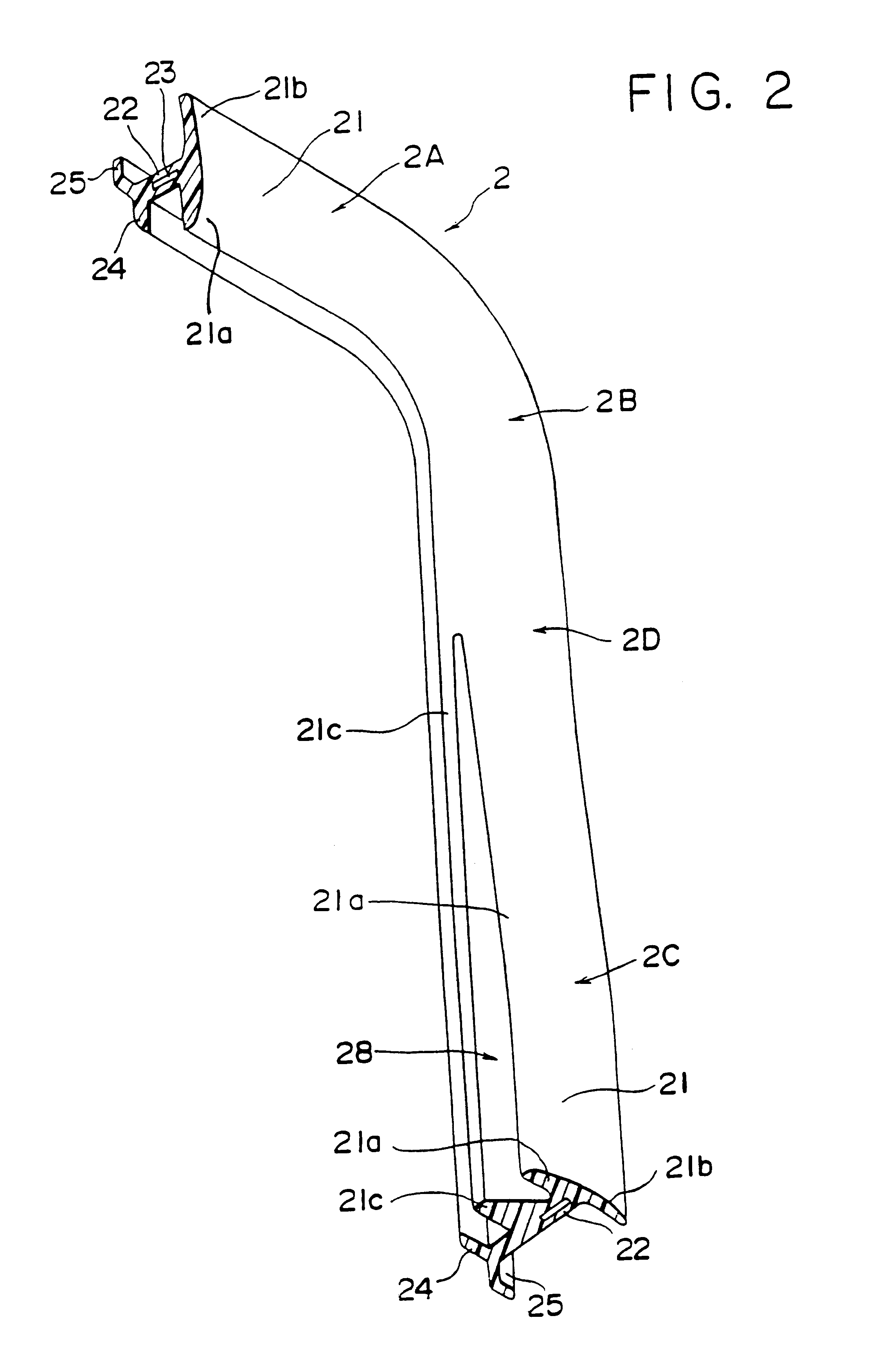
The molding 2 is a long plastic strip in the shape of a T, and an upper molding part 2A to be mounted between the upper edge of the windshield and the roof panel 12, side molding parts 2C between side edges of the windshield 11 and pillar panels 13 of the vehicle body, and corner molding parts 2B for connecting the upper and side molding parts 2A and 2B. All of these molding parts 2A and 2B are extruded as one unit.

Each of the side, corner and upper molding parts 2A to 2C comprises an exterior wing 21 adapted to cover a space, on the exterior side of the vehicle, between the window-opening periphery of the vehicle body panel and each of the side, corner and upper edges of the windshield.

The exterior wing 21 includes an inward wing portion 21a for covering...

second embodiment

the invention will be described referring to FIGS. 9 to 12.

FIG. 9 is a cross-sectional view showing a windshield molding 4 according to the second embodiment. The molding 4 comprises a pair of extruded side molding parts 4C, a pair of extruded corner molding parts 4B, and an extruded upper molding part 4A integral with and extending between the side and corner molding parts.

Each of the molding parts 4A, 4B and 4C includes an exterior wing 41 and a connecting portion 42. The exterior wing 41 has an inward wing portion 41a and an outward wing portion 41b. The outward wing portion 41b has a uniform shape and thickness throughout the molding parts 4A to 4C.

The connecting portion 42 has a foot 44 extending inwardly along the lower end thereof. The foot 44 has a forked portion 444 at its end. One of the forked portion 444 contacts with the lower side of the windshield 11, and another of the forked portion 444 contacts with the side of the windshield 11. Namely, the forked portion 444 cont...

third embodiment

FIGS. 14 to 17 show the invention. As shown in FIG. 14, a molding 9 comprises a pair of extruded side molding parts 9C, a pair of extruded corner molding parts 9B, and an extruded upper molding part 9A integral with and extending between the side and corner molding parts.

Each of the molding parts 9A, 9B and 9C includes an exterior wing 91 and a connecting portion 92. The exterior wing 91 has an inward wing portion 91a and an outward wing portion 91b.

As shown in FIG. 14, the connecting portion 92 includes a foot 94 extending inwardly along the lower end thereof. At the upper molding part 9A, the upper edge of the windshield 11 is received in the space formed by the foot 94 and the inward wing portion 91a. At the majority of the side molding part 9C, the inward wing portion 91a is gradually projected to the exterior direction to form a sub-inward wing portion 91c thereunder. A water drain channel 98 is formed between the inward wing portion 91a and the sub-inward wing portion 91c. The...


PUM


Abstract

A windshield molding which is installable in the space between a windshield and a periphery of a window opening of a vehicle body panel. The windshield molding includes a pair of extruded side molding parts, a pair of extruded corner molding parts, and an extruded upper molding part integral with and extending between the side and corner molding parts. Each of the side molding parts associated with each side edge of the windshield is greater in thickness as compared with the upper end corner molding parts, where a water drain channel is formed. A windshield molding is also provided which drains rainwater smoothly through the rainwater groove provided at necessary sections and having a different depth in the longitudinal direction for better drainage which can be produced simply and continuously as a single molding without the addition of cutting or other processes.

Description

FIELD OF THE INVENTIONThis invention relates to an automobile windshield molding for a motor vehicle body to seal the space between a windshield and a periphery of a window opening of a vehicle body panel, and a method of producing such automobile windshield molding.DESCRIPTION OF THE RELATED ARTAn automobile windshield molding is usually attached around an edge of a windshield to seal the space between a windshield and a window opening of a vehicle body panel. The automobile windshield molding is directly attached to the vehicle body panel or is supported by a fastener fixedly mounted on the body panel.Examples of such molding are disclosed in Japanese Utility Model Publication No. 54416 / 1982 and Japanese Utility Model Laid-Open Publication No. 9811 / 1989. These citations disclose windshield moldings which have water drain channels for receiving water flowing on the surface of the windshield.Japanese Patent Laid-Open Publication 289427 / 1987 and Japanese Utility Model Laid-Open Publi...

Claims


Application Information

Patent Timeline
Patent Type & Authority Patents(United States)
IPC IPC(8): B60J10/02
CPCB60J10/0071B60J10/02B60J10/34B60J10/70
Inventor YADA, YUKIHIKO
Owner TOKAI KOGYO CO LTD
Why Eureka
Try Eureka