Drive system, especially for a motor vehicle, and method of operating same

a technology of drive system and motor vehicle, which is applied in the direction of gearing control, mechanical energy handling, electric energy vehicles, etc., can solve the problems of slow and sluggish engine adjustment, slow and steady drive wheel rotation speed rise, and difficult overall drive slip control

Inactive Publication Date: 2001-03-13
CONTINENTAL ISAD ELECTRONICS SYST GMBH & CO KG +1
View PDF136 Cites 47 Cited by
  • Summary
  • Abstract
  • Description
  • Claims
  • Application Information

AI Technical Summary

Benefits of technology

The advantages of such a drive slip control lie in that the drive slip control works quickly and not sluggishly and, thus, the reduction of the drive slip is ideally controllable. Thus, traffic safety is also improved on the whole.
To minimize the electrical losses, the torque transmitters which separate the electromagnetic coupling, can be connected advantageously to a bridge coupling, especially a mechanical coupling. This may involve, for example, a friction-closure coupling or--since it can always be coupled in by appropriate control with vanishing clutch slip--advantageously a positive-closure coupling, such as a claw clutch. Instead of providing a separate coupling, it is also possible to bring the two rotors of the dual machine or the two active units of the single machine into friction or positive closure with each other by axial shifting.

Problems solved by technology

As it continues to increase, however, the force closure is again reduced, so that an excess drive torque becoming larger under corresponding acceleration leads to a fast rise in rotary speed of a drive wheel or the drive wheels.
The drawback to these known drive slip controls is that, first, the engine adjustment is slow and sluggish and, secondly, the overall drive slip control is hard to manage, i.e., it is almost never possible to achieve a particular decrease in drive torque over time.

Method used


Image

  • Drive system, especially for a motor vehicle, and method of operating same
  • Drive system, especially for a motor vehicle, and method of operating same
  • Drive system, especially for a motor vehicle, and method of operating same

Examples


Embodiment Construction

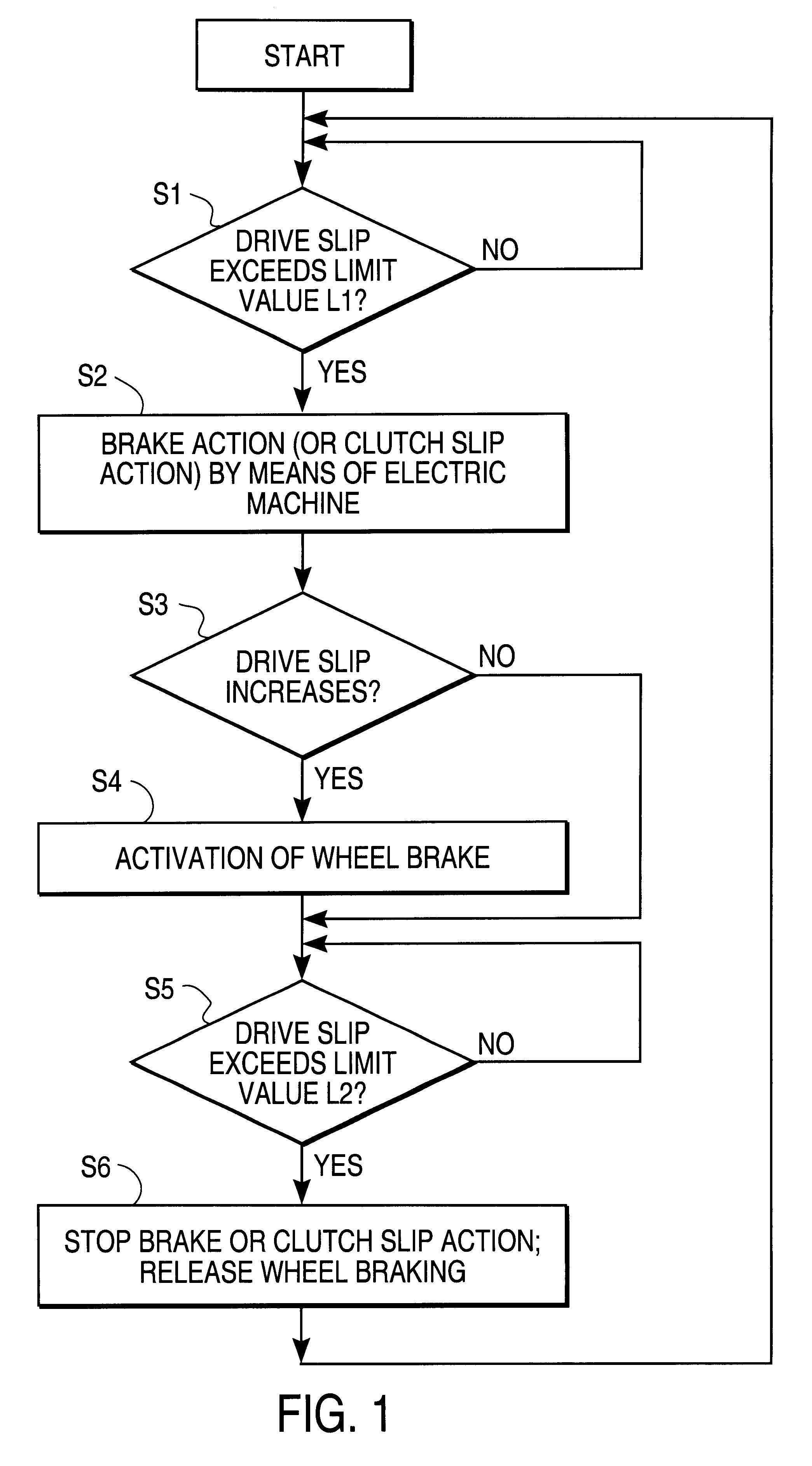
The invention is based on the technical problem of modifying and improving the known drive slip controls.

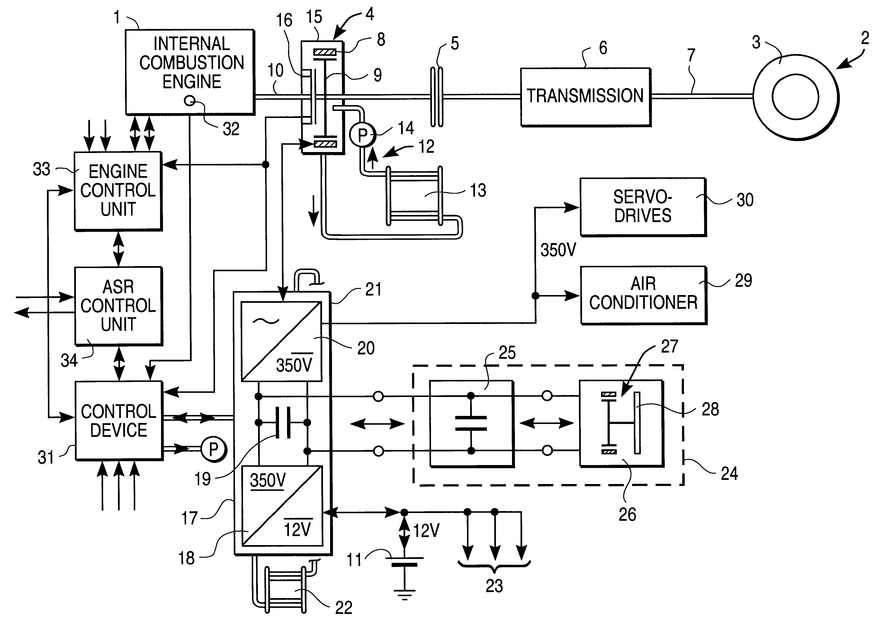
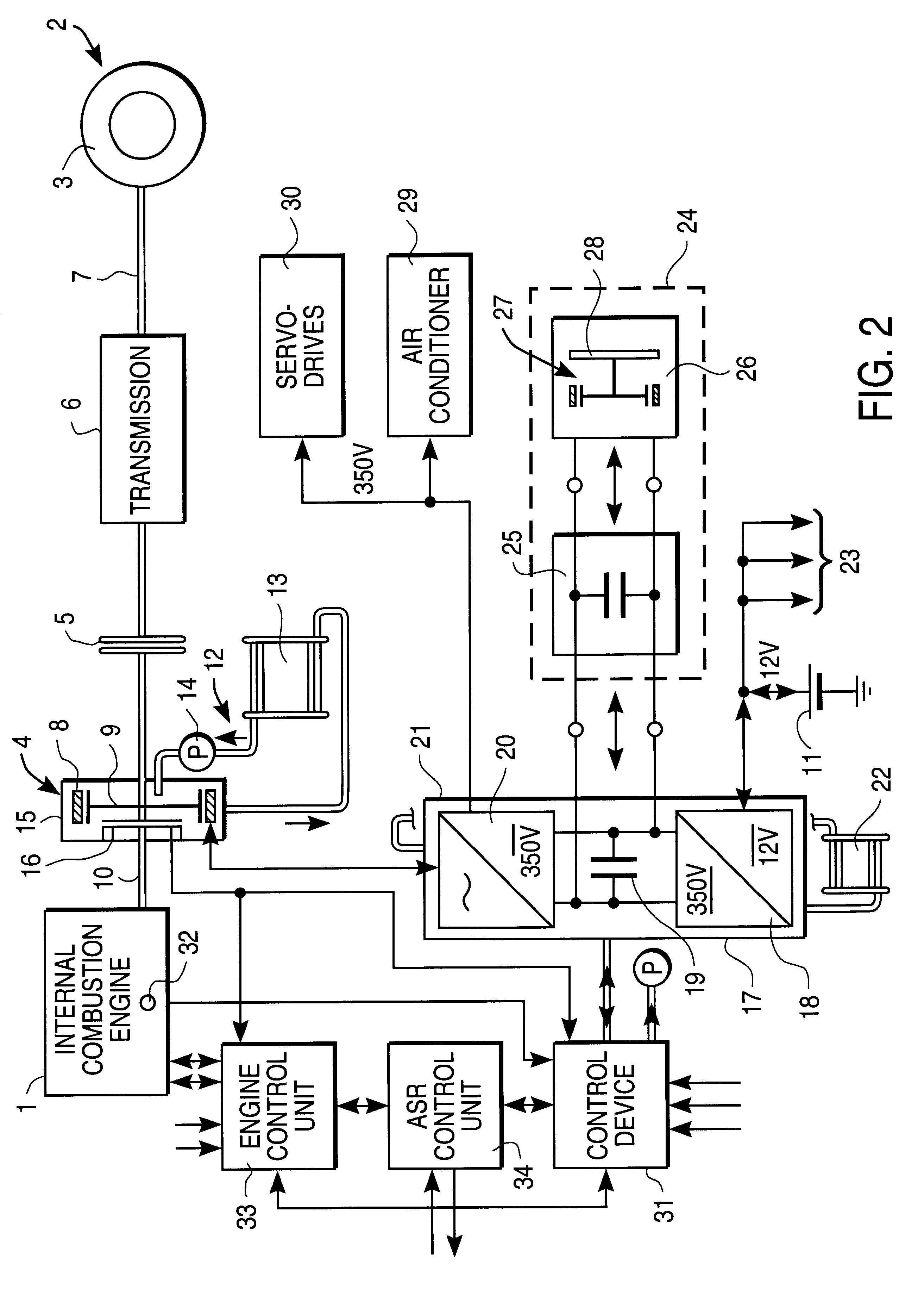
This problem is solved by a drive system, with a drive slip control, in which the (or one) electric machine is designed such that it can produce a reduction in drive slip by decreasing the drive torque (of the drive assembly), in particular, by braking action and / or--when the electric machine acts as a coupling--by clutch slip action (claim 1).

In the drive system according to the invention, the drive slip reduction is generally active only when--as in the state of the art--a certain condition is fulfilled. This condition can be the exceeding of a limit value of the drive slip or a limit value of the change in the drive slip over time. But the condition can also be defined more complexly, say, in the sense of a combination of both of the above-mentioned conditions, or even other conditions.

If, now, a defined condition is fulfilled, the drive moment acting on the drive wheels is re...


PUM


Abstract

Drive system, especially for a motor vehicle, with a drive assembly, especially an internal combustion engine (1), an electric machine (4) and an antislip control, in which the (one) electric machine (4) is designed such that it can produce a reduction of drive slip, in particular by braking action and / or-when the electric machine (4) is acting as a coupling-by clutch slip action.

Description

1. Field of the InventionThe invention concerns a drive system, especially for a motor vehicle, and a method of operating same.2. Description of the Related ArtBasically, the transmission of force in motor vehicles--which is responsible for the forward movement of the vehicle--depends on drive slip between tires and road. In general, the starting and acceleration processes occur at low slip values, during which an increase in slip also produces an increase in the useable force closure at first. As it continues to increase, however, the force closure is again reduced, so that an excess drive torque becoming larger under corresponding acceleration leads to a fast rise in rotary speed of a drive wheel or the drive wheels.A regulating of the drive slip, i.e., a so-called drive slip control (ASR), prevents such a spinning of the drive wheels and regulates the drive slip down to permissible values. Such drive slip controls are known in the state of the art (see, for example, "Automotive H...

Claims


Application Information

Patent Timeline
Patent Type & Authority Patents(United States)
IPC IPC(8): B60K6/04B60L11/12B60L7/28B60K6/00B60K6/06B60L11/02B60L7/00B60T1/00B60T1/10B60K28/16F02B75/00F02B75/06F02N11/08F16F15/18F16F15/10F02B67/04F16F15/12F16F15/129H02K7/10H02K51/00H02K7/108F16H61/04B60K6/26B60K6/38B60K6/387B60K6/442B60K6/48B60L50/15B60L50/16B60T8/175B60W10/02B60W10/04B60W10/06B60W10/08B60W10/18B60W20/00F16D48/06H02P7/00
CPCB60K6/26B60K6/387B60K6/442B60K6/48B60K28/16B60L7/003B60L7/28B60L11/12B60T1/10B60W10/06B60W10/08B60W10/18B60W20/00F02B67/04F02B75/06F16F15/1292F16F15/18H02K7/108H02K51/00B60K6/38Y10T74/19153B60K2001/003B60K2006/262B60L2220/52B60L2240/443B60W2510/0657F02D2250/24F02N11/04F02N11/0814F02N11/0866F16H2061/0422Y02T10/6221Y02T10/6234Y02T10/6286Y02T10/641Y02T10/7077Y10S903/946Y10S903/906Y10S903/914Y10S903/947Y10S903/96Y10S903/912B60L2200/26B60K2006/268B60L3/106B60W30/18172B60L50/16Y02T10/62Y02T10/64Y02T10/7072B60W20/15Y02T10/70
Inventor MASBERG, ULLRICHPELS, THOMASZEYEN, KLAUS-PETERGRUNDL, ANDREASHOFFMANN, BERNHARD
Owner CONTINENTAL ISAD ELECTRONICS SYST GMBH & CO KG
Why Eureka
Try Eureka