Laser system for marking or perforating

a laser system and laser technology, applied in the field of laser system for marking or perforating, can solve the problems of difficult operation, low accuracy of conventional headstocks, and difficult adjustment of focal distance, and achieve the best safety and accuracy of optical systems and deflection, and easy adjustment of focal distance.

Inactive Publication Date: 2001-03-13
MACSA ID
View PDF7 Cites 9 Cited by
  • Summary
  • Abstract
  • Description
  • Claims
  • Application Information

AI Technical Summary

Benefits of technology

The invention has the object to provide a marking or piercing system offering a best safety and accuracy of the optical syst

Problems solved by technology

The fixed optical system which is provided with a headstock does not allow the lens to move with the aim of optimizing the focal point.
For such aim, all the system is to be moved, which means a not very accurate adjustment of the focal distance and hard to perform because of the system weight.
In a production line, where applications may be very different, there is usually varying sizes of the products to be marked, therefore the availability of adjusting the focal lens position is required to keep the focal distance with respect to the surface to be marked or changing very often the lens, a fact that with the conventional headstocks is very spectacular and little accurate.
On the other hand, the position of the element which blocks the non deflected beam exit, which is not in direct contact with the headstock, is dilated because it is heated by the laser action, a fact which makes rise to a significant reduction of movement flexibility.
It must also be stated that Bragg's angle adjustment system shows problems because the tilting wheel and the part where the deflector is fitted are in contact through a cylindric shaft which allows the movement between these two parts and the headstock wall, which causes a difficulty to a perfect blocking which may give rise to

Method used


Image

  • Laser system for marking or perforating
  • Laser system for marking or perforating
  • Laser system for marking or perforating

Examples


Embodiment Construction

There is below a description of the invention based on above mentioned figures.

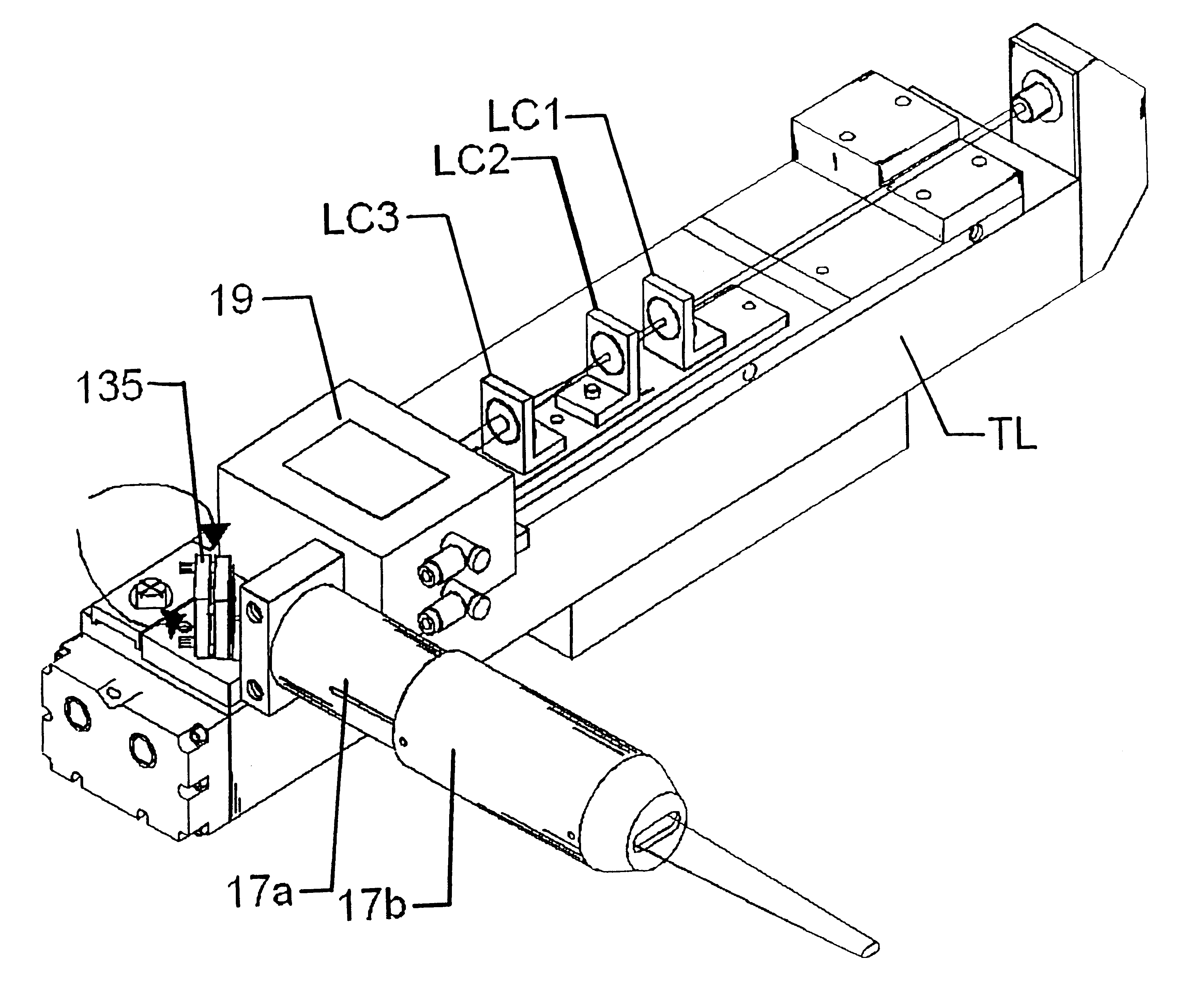
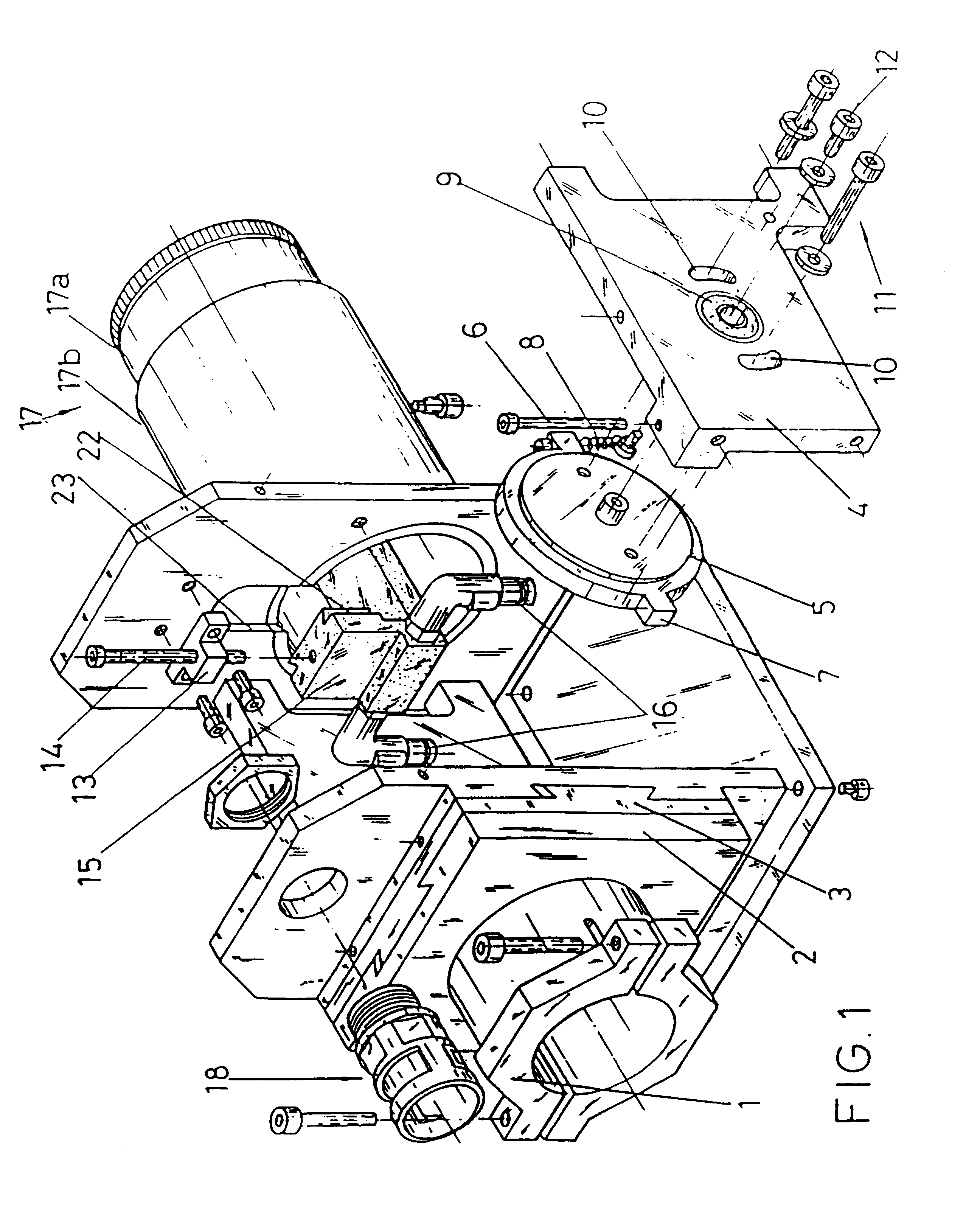
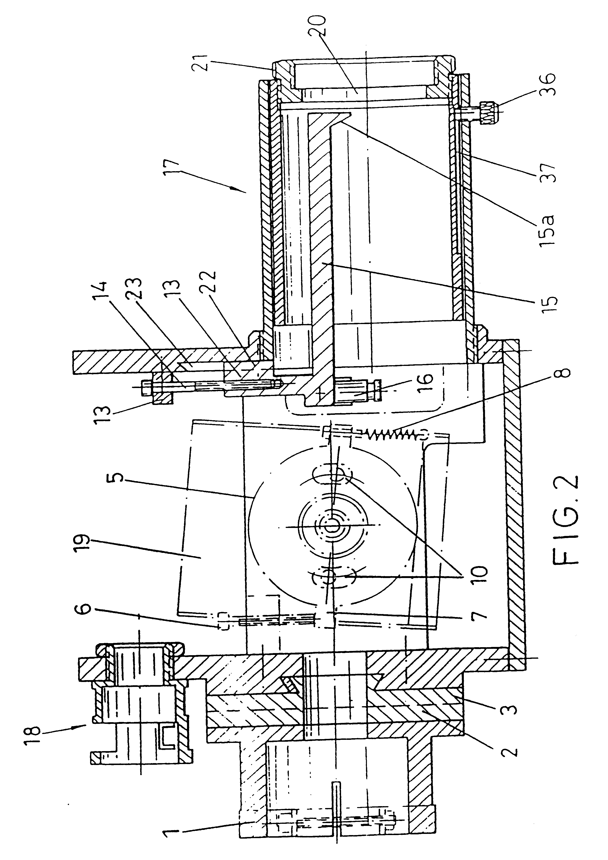
First, and with the assistance of FIGS. 1 and 2, a first example of embodiment of the invention is disclosed, in which the headstock is attached to the laser tube with possibility of moving along X and Y axes, for which the headstock includes two strips 2 and 3 which are provided with "fly wing-like" mechanizations, so that the strip 2 can be moved in vertical sense (Y axis) and the strip 3 in horizontal sense (X axis). The laser tube is attached by means of a clamp 1 with which by moving the strips 2 and 3 it is allowed to focus the laser beam in the opening of a deflector 19 inlet (FIG. 2).

The deflector 19 remains located within the headstock and is directly fitted on a tilting wheel 5 the central axis of which is located in a socket 9 provided in one of the headstock side walls.

Sideways to the socket 9 on the side wall two associated holes 10 have been provided located diametrically opposite in corresp...


PUM

PropertyMeasurementUnit
Lengthaaaaaaaaaa
Angleaaaaaaaaaa
Diameteraaaaaaaaaa

Abstract

A laser system for marking or perforating, including a laser tube and a head having an adjustable optical system with at least one focusing lens. The telescopic tube, a system of lenses for the light beam correction, and a deflexion system are integrally provided with the laser tube. In order to easily optimize the focal distance, a focusing lens is situated in a mobile tube of the telescopic tube which includes a mobile tube (17b) and a fixed tube (17a).

Description

DESCRIPTIONThe invention is applicable to every laser marking or piercing system, such as lines for dynamic marking with which characters, bar codes, logos, etc. are marked in products.STATE OF THE ARTThe use of laser marking systems is known to print characters, logos, bar codes, etc. in products which are carried on a production line, for which the headstock includes an acoustical-optical deflector on which the laser beams is incident to which a radiofrequency signal is applied which produces a laser beam deflection according to different angles whoses value depends on the frequency applied, i.e., with different frequencies different deflection angles are obtained.There exists a kind of headstock which fastens the laser tube by means of a set of strips provided with "fly wing-like" or other mechanisms allowing that the headstock moves according to XY axis to focus the laser beam on the acoustical-optical deflector inlet window.The acoustical-optical deflector is fitted on a metall...

Claims


Application Information

Patent Timeline
IPC IPC(8): B23K26/02G02B27/09B23K26/00
CPCB23K26/02B23K26/026B23K26/035
Inventor LLADO ABELLA, JORDI
Owner MACSA ID
Why Eureka
Try Eureka