Fluid sample distriution system for test device

a technology of distribution system and test device, which is applied in the direction of analysis using chemical indicators, laboratory glassware, instruments, etc., can solve the problems that no such product has even been successfully produced, marketed and/or sold

Inactive Publication Date: 2001-03-20
BIONIKE
View PDF6 Cites 107 Cited by
  • Summary
  • Abstract
  • Description
  • Claims
  • Application Information

AI Technical Summary

Benefits of technology

It is further emphasized that the delivery of an aliquot of test fluid to each test strip by a given branch of the sample receiving web is to a different location on each test strip within the test device, depending upon its relative position within the housing; and, that as the fluid is absorbed into each of the test strips at each of those two separate locations, the apparent volume of fluid within each test strip becomes essentially balanced, so as to cause such fluid to contact the test site of each test strip at essentially the same point in time. This passive manipulation and distribution of the fluid sample to multiple test strips afford essentially concurrent (simultaneous) performance of a panel of assays on a common sample within a simple and unitary test environment.
In the preferred embodiments of this invention, each of the test strips within the test device is specific for a discrete (different) anal

Problems solved by technology

This so-called "profile" analysis of a common test sample has also been postulated as capable for performance on a manu

Method used


Image

  • Fluid sample distriution system for test device
  • Fluid sample distriution system for test device
  • Fluid sample distriution system for test device

Examples


Embodiment Construction

The device of this invention as illustrated in the foregoing Figures includes a number of elements in common and, thus, for the purpose of ease of understanding each of these common elements are referenced with a common numeral or designation.

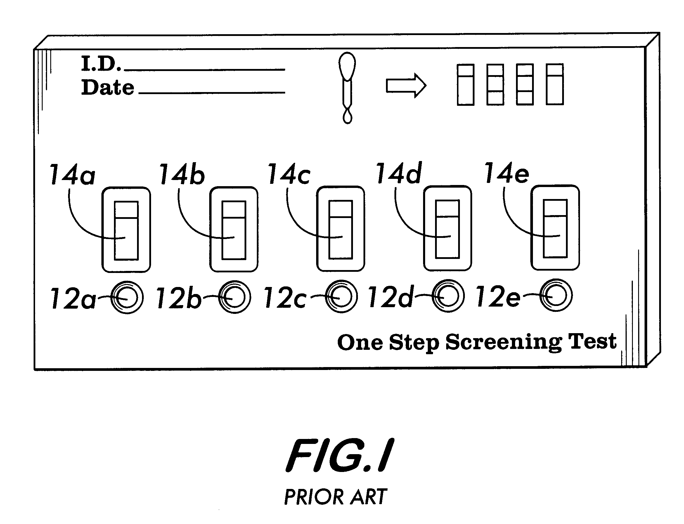
FIG. 1 is typical of the prior art and is illustrated herein for purposes of comparison to the structure, function and operation of the device and system of the instant invention. More specifically, the prior art device illustrated in FIG. 1 includes a series of discrete sample application / receiving site (12) that directs the uptake and distribution of an aliquot of the sample (13) to each of the individual test strips (14). As is evident from the placement of the test strips in this device, the sample is distributed by a wicking and / or capillary action from the discrete sample application / receiving, site (12) to the test site and, thereafter, the results observed by monitoring for perceptible changes in the viewing window. In addition, this de...


PUM


Abstract

Diagnostic products having multiple test strips within a unitary diagnostic test device, or test icon, are described herein. In the preferred embodiments of the diagnostic test device of this invention, a fluid sample distribution system is provided wherein a sample collection and distribution port is provided in the housing for receipt of a biologic fluid sample and the channeling of such sample onto a sample receiving web. The sample receiving web, which is located within the test device, is in fluid communication with an array of test strips, and is configured to deliver an aliquot of biologic fluid sample to the test site of each such test strip at essentially the same rate. In the preferred embodiments of this invention, the sample receiving web comprises at least one base segment and at least one branched segment. Each of the base and branched segments can be formed or cut from a common sheet of material or from separate sheet material and thereafter placed in contiguous relationship one another. The relative placement of the sample receiving web within the test device is coincident with a portion of each test strip and designed to effect the balanced distribution and delivery of an aliquot of the biologic fluid sample to the test site of each of the test strips within the test device.

Description

1. Field of the InventionThis invention is directed to a fluid sample distribution system for a test device. More specifically, this invention relates to a system and device for concurrent performance of multiple discrete analysis on a common test fluid by the passive and balanced distribution of the test fluid to the discrete test strips within the device.2. Description of the Prior ArtThe increasing popularity of simple and rapid diagnostic test kits for self-testing, and for use in professional environments devoid of elaborate instrumentation for sample preparation and analysis, has become increasingly prevalent because of the accuracy and relatively modest costs involved in the use of such products. Generally all of these products share the following common components, test format and performance criteria:(a) a porous or bibulous medium for receipt of the sample, (which may also provide a source of test kit reagent for analysis of the sample),(b) a test strip specific for detect...

Claims


Application Information

Patent Timeline
IPC IPC(8): G01N33/558G01N33/543
CPCG01N33/54366G01N33/558Y10S436/901Y10S436/815
Inventor LU, FRANKCHAN, LIANG
Owner BIONIKE
Why Eureka
Try Eureka