Dumping device of catalyst inside reactor and dumping method using the same

a technology of dumping device and catalyst, which is applied in the direction of catalyst regeneration/reactivation, physical/chemical process catalyst, bend, etc., can solve the problems of deteriorating work efficiency, difficult unloading work, and difficult unloading work in the reactor

Inactive Publication Date: 2001-03-20
SOFTARD IND CO LTD 17 7 MISONOCHO 1 CHOME KODAIRA SHI TOKYO JAPAN
View PDF5 Cites 42 Cited by
  • Summary
  • Abstract
  • Description
  • Claims
  • Application Information

AI Technical Summary

Problems solved by technology

Such catalysts have to be periodically unloaded from the reactor to be exchanged, since activity of the catalyst gets weak as the catalysts are poisoned by sedimentation of carbide, metal or the like and the catalysts are smashed on account of lowering of mechanical strength.
In this case, the unloading work is difficult on account of a high temperature of the reactor.
Further, when the work is carried out in the nitrogen gas atmosphere, the unloading work is difficult to be performed in the reactor.
Accordingly, long time is necessary for the unloading work of the catalyst inside the reactor, so that the work efficiency is deteriorated and the plant shut-down time is prolonged.
Accordingl

Method used


Image

  • Dumping device of catalyst inside reactor and dumping method using the same
  • Dumping device of catalyst inside reactor and dumping method using the same
  • Dumping device of catalyst inside reactor and dumping method using the same

Examples


first embodiment

of the present invention is shown in FIGS. 1 to 8.

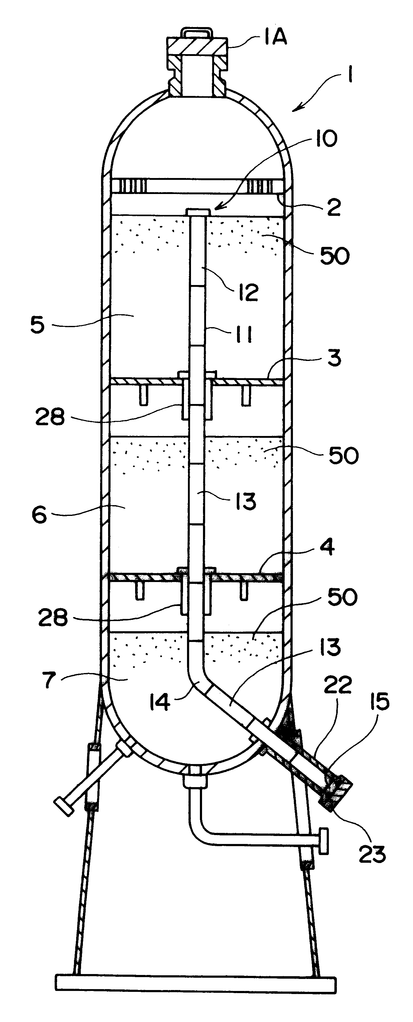
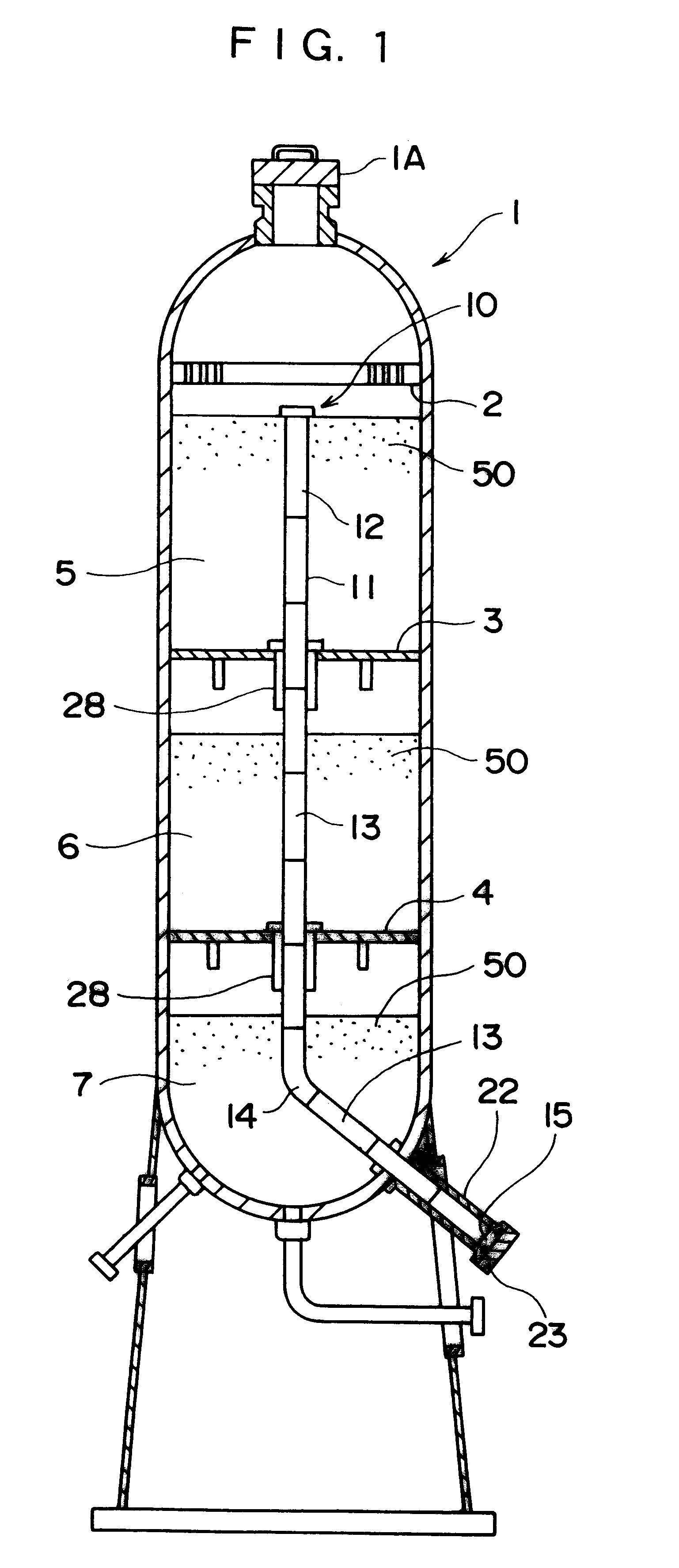
A dumping device 10 is provided to a reactor 1 in which a plurality of sorts of material is reacted at a predetermined temperature and pressure condition.

The reactor 1 has a three-bed structure composed of an upper bed 5, a middle bed 6 and a lower bed 7, each partitioned by first internals 2, second internals 3 and third internals 4. A catalyst 50 is filled in the middle bed 6 and the lower bed 7.

A manhole 1A is provided on an upper portion of the reactor 1 and a catalyst dumping nozzle 22 is provided on a lower portion of the reactor 1. When the catalyst is unloaded from the reactor 1 and when the catalyst is agglomerated inside the reactor 1, oil or a chemical agent is injected from the manhole 1A to form a film onto the catalyst for preventing oxidization of the catalyst. And a pressure introducing hose is put into the reactor 1 when an air pick is used for smashing the agglomerated catalyst.

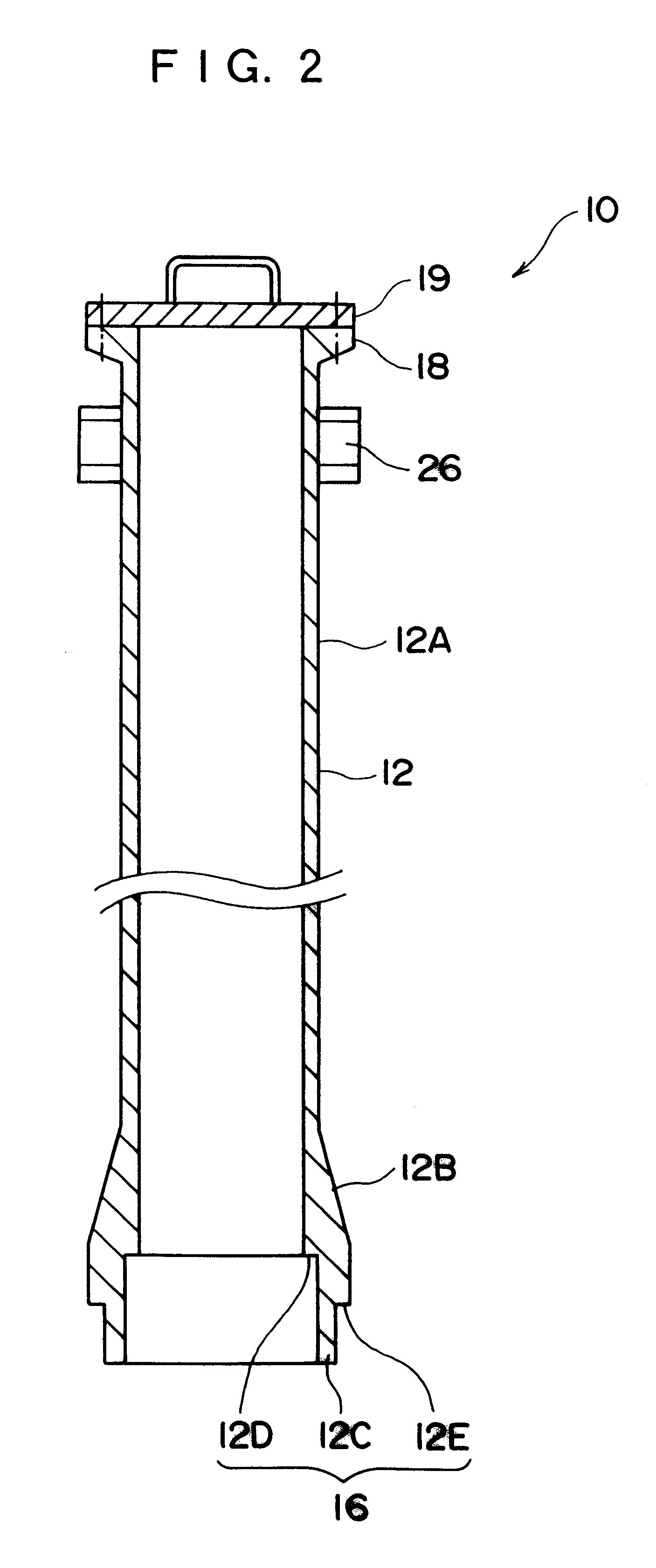
The dumping device 10 has a dumping pi...

second embodiment

of the present invention will be described below with reference to FIGS. 9 and 10.

The dumping device 10A according to the second embodiment has a dumping pipe 31 perpendicularly placed eccentrically to the center of the reactor 1 in contrast to the dumping pipe 11 of the first embodiment located perpendicularly at the center of the reactor 1. A pipe member 33 provided to the lower end of the dumping pipe 31 is inserted to a catalyst dumping nozzle 22A attached perpendicularly outside the reactor 1.

According to the present embodiment, only a pipe member connected to the pipe-receiving member 15 is different from the pipe members of the first embodiment and the other construction is the same. Accordingly, only different part will be described below and the same reference numeral will be applied to the same members for omitting or simplifying the description.

As shown in FIG. 10, the lower pipe member 33 connected to the pipe-receiving member 15 has substantially the same configuration ...


PUM

PropertyMeasurementUnit
Pressureaaaaaaaaaa
Diameteraaaaaaaaaa
Densityaaaaaaaaaa

Abstract

A catalyst dumping device (10) for unloading a catalyst (50) inside a reactor (1), in which smashed used catalyst is thrown into a dumping pipe (11) formed of a plurality of pipe member (12) provided to the reactor (1) to unload to outside of the reactor (1) by fall by dead weight. Accordingly, the catalyst can be unloaded only by throwing the catalyst into the dumping pipe (11), thereby improving work efficiency. Furthermore, no special apparatus such as a vacuum apparatus is unnecessary, thereby reducing cost for the special apparatus.

Description

1. Field of the InventionThe present invention relates to a dumping device and a dumping method for unloading used catalyst adhered and agglomerated inside a reactor of petroleum refining plant, chemical plant and the like.2. Description of Related ArtVarious catalysts are used in a petroleum refining plant, chemical plant and the like for facilitating chemical reactions. The catalysts are used being filled inside a reactor for circulating fluid material.Such catalysts have to be periodically unloaded from the reactor to be exchanged, since activity of the catalyst gets weak as the catalysts are poisoned by sedimentation of carbide, metal or the like and the catalysts are smashed on account of lowering of mechanical strength. The catalysts also need to be unloaded from the reactor for repairing or examining the plant.[Unloading Condition of Catalyst]The catalysts need to be unloaded in a short time period for minimizing plant shut-down time.Further, since the catalyst in operation i...

Claims


Application Information

Patent Timeline
IPC IPC(8): B01J8/04B01J8/00B01J38/00B65G65/40B01J8/02
CPCB01J8/003B01J8/0035B01J8/0453B01J38/00Y10S285/901
Inventor KAWAKAMI, KATSUHIKOSAWAMURA, NOBUYOSHINAGATA, SHINICHI
Owner SOFTARD IND CO LTD 17 7 MISONOCHO 1 CHOME KODAIRA SHI TOKYO JAPAN
Why Eureka
Try Eureka