Sodium secondary battery

Inactive Publication Date: 2001-03-27
MITSUBISHI HEAVY IND LTD
View PDF5 Cites 11 Cited by
  • Summary
  • Abstract
  • Description
  • Claims
  • Application Information

AI Technical Summary

Problems solved by technology

(2) Under the aforementioned conditions (i.e., high temperature and in vacuo), pressurization must be performed, which raises disadvantages associated with scaling up of the apparatus employed and an increase in the number of manufacturing steps, such as cooling from high temperatures and raising pressure from the vacuum condition to atmospheric pressure.
(4) Conventional planar-type sodium secondary batteries suffer a problem

Method used


Image

  • Sodium secondary battery
  • Sodium secondary battery
  • Sodium secondary battery

Examples


embodiment 1

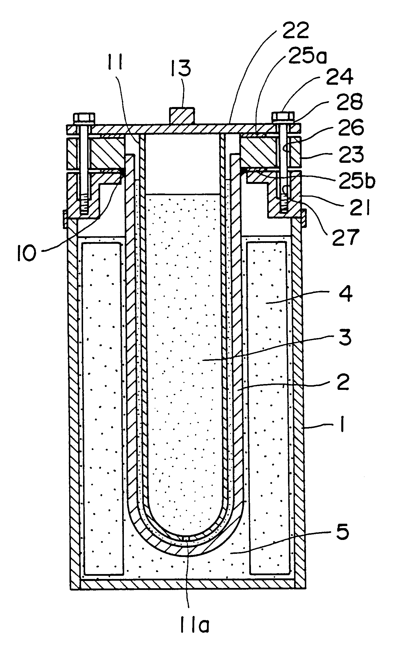
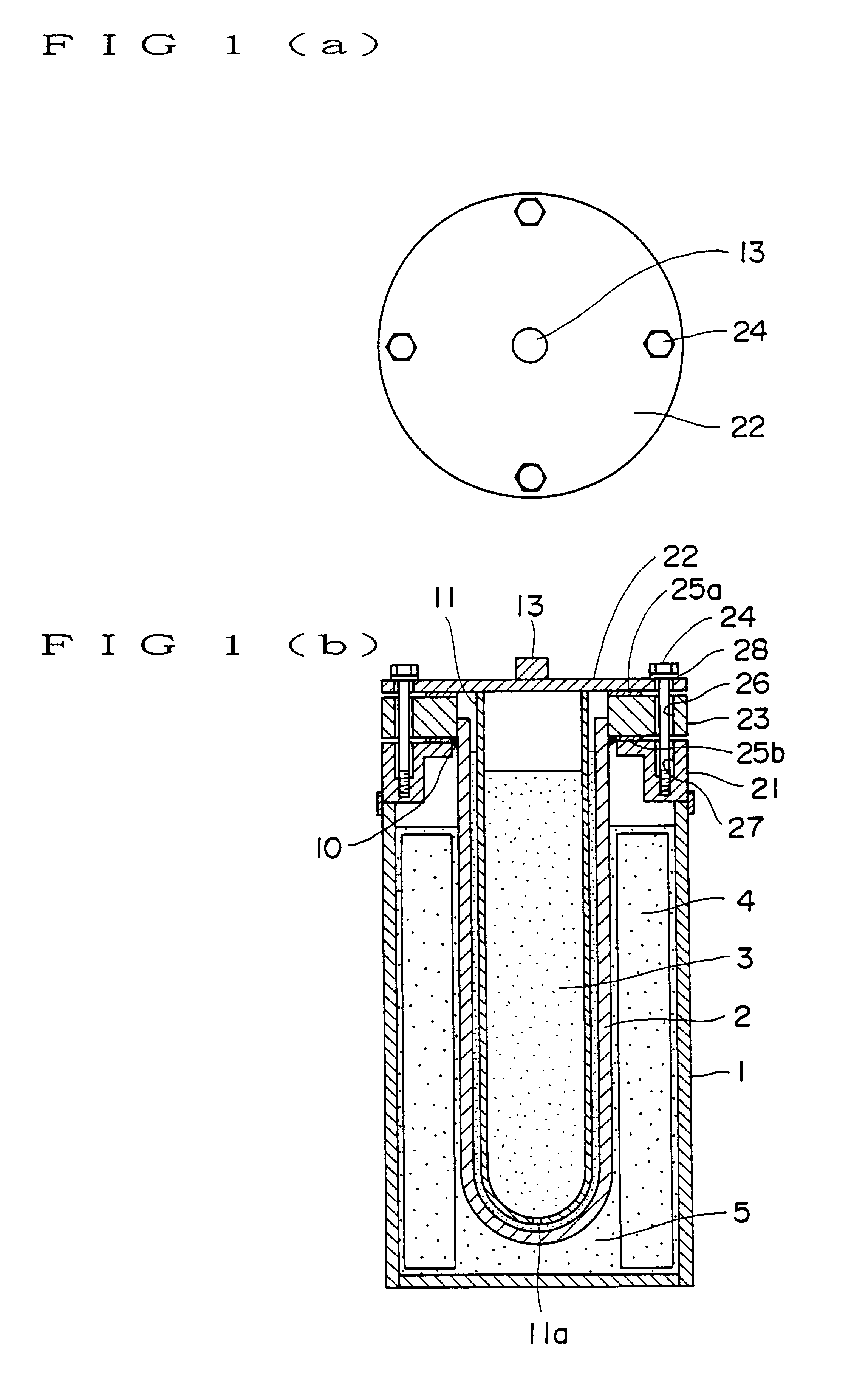
FIG. 1A and FIG. 1B are a schematic illustration of a sodium secondary battery according to a first embodiment of the present invention.

As shown in FIG. 1A and FIG. 1B, the sodium secondary battery, according to the first embodiment of the present invention, has a structure the same per se as that of the conventional secondary battery, as shown in FIG. 9, but has an outer case sealed with a cover in a different manner to provide improved sealing of the battery.

The sodium secondary battery, according to the first embodiment of the present invention, has a negative electrode chamber formed by placing sodium 3 into a bottom-closed, hollow cylindrical solid electrolyte 2 provided inside an outer case 1. A positive electrode chamber, which houses a porous electrode 4 impregnated with sulfur 5, serving as a positive electrode active substance is provided, between the outer case 1 and the solid electrolyte 2. A cover 22, which closes an outer case metal fitting 21 provided for the opening ...

embodiment 2

FIG. 3 is a schematic illustration of a plate-type sodium secondary battery according to a second embodiment of the present invention.

As shown in FIG. 3, the sodium secondary battery, according to the second embodiment of the present invention, includes a negative electrode chamber in which sodium 31 is placed, a positive electrode chamber which houses a porous electrode 32 impregnated with sulfur 33, and a plate-like solid electrolyte 30 interposed therebetween. The negative electrode chamber is defined by a negative electrode container 35 having an outwardly projecting flange 34 and the positive electrode chamber is defined by a positive electrode container 37 having an outwardly projecting flange 36, and the negative and positive electrode containers 35 and 37 are located opposite to each other with respect to the solid electrolyte 30. An insulator 38 is provided along the periphery of the solid electrolyte 30, and the outwardly projecting flange 34 of the negative electrode and ...

embodiment 3

FIG. 7 is a schematic illustration of a sodium secondary battery according to a third embodiment of the present invention.

As shown in FIG. 7, the sodium secondary battery, according to the third embodiment, has a battery structure the same per se as that shown in FIG. 1A and FIG. 1B, but provides improved sealing due to the employment of a different fastening manner of a cover and a case. Briefly, an outer case 1 is fastened to a cover 22 by bolts and nuts, with the bolts being arranged so as not to penetrate an insulator, to thereby provide improved sealing.

The sodium secondary battery according to the third embodiment has a negative electrode chamber formed by placing sodium 3 into a bottom-closed, hollow cylindrical solid electrolyte 2 provided inside an outer case 1. A positive electrode chamber, which houses a porous electrode 4 impregnated with sulfur 5 serving as a positive electrode active substance is provided between the outer case 1 and the solid electrolyte 2. A cover 22...


PUM


Abstract

A sodium secondary battery which assures excellent sealing and can be manufactured in a simple manner is provided. The battery includes a negative electrode chamber defined by the inside of a bottom-closed, hollow cylindrical, solid electrolyte accommodated in an outer case and a positive electrode chamber formed outside the solid electrolyte and containing a porous electrode 4 impregnated with sulfur which serves as a positive electrode active substance. A cover, which closes the opening portion of the outer case, is fastened to the outer case by use of bolts and the interposition of an insulator.

Description

1. Field of the InventionThe present invention relates to a sodium secondary battery which is sealed in an improved manner, and in particular to a rechargeable secondary battery applied to batteries for storage of electric power for road grading and to electric vehicles.2. Background ArtFIG. 9 (PRIOR ART) is a schematic illustration of a conventional sodium secondary battery.As shown in FIG. 9, in the conventional sodium secondary battery, a negative electrode chamber is formed by placing sodium 3 into a bottom-closed, hollow cylindrical solid electrolyte 2 provided inside an outer case 1; and between the outer case 1 and the solid electrolyte 2 is disposed a porous electrode 4 impregnated with sulfur 5 serving as a positive electrode active substance, to thereby form a positive electrode chamber. An outer case metal fitting 6 having an L-shaped cross section is welded to the opening portion of the outer case 1. For a cover 12, a metal fitting (hereinafter referred to as a cover met...

Claims


Application Information

Patent Timeline
IPC IPC(8): H01M10/36H01M10/39H01M2/04
CPCH01M2/0447H01M10/3909H01M10/3963H01M10/3981H01M50/1535Y02E60/10Y02P70/50
Inventor FUKAGAWA, MASAYUKIIWAMOTO, KEIICHIKAWASETSU, NOZOMUSUDOU, KATSUZOUSAWATA, AKIHIRO
Owner MITSUBISHI HEAVY IND LTD
Why Eureka
Try Eureka