Turbofan engine including fans with reduced speed

a technology of reducing speed and turbine engine, which is applied in the direction of machines/engines, sustainable transportation, mechanical equipment, etc., can solve the problems of reducing the efficiency of the propeller of the fan, increasing the peripheral speed of the fan, and generating shock waves

Inactive Publication Date: 2001-04-03
NIKKISO COMPANY
View PDF15 Cites 102 Cited by
  • Summary
  • Abstract
  • Description
  • Claims
  • Application Information

AI Technical Summary

Problems solved by technology

However, as the outer diameter of the fan increases, the peripheral speed of the fan increases and shock waves are produced when the speed approaches that of sound.
This results in a lowering of the propeller efficiency of the fan, which in turn leads to a decline in overall efficiency.
If the rotational speed of the fan is simply lowered, the rotational speed of the turbine in the core engine which directly drives the fan is also lowered, resulting in a decrease in turbine efficiency.
Consequently, thermal efficiency of the core engine is also declined, thereby decreasing the overall efficiency.
Material for the gear mechanism is relatively heavy because of durability requirements.
If its weight is reduced, rigidity of the gear mechanism will be diminished, giving rise to great deflection of components.
Such deflection makes it extremely dif...

Method used


Image

  • Turbofan engine including fans with reduced speed
  • Turbofan engine including fans with reduced speed
  • Turbofan engine including fans with reduced speed

Examples


first embodiment

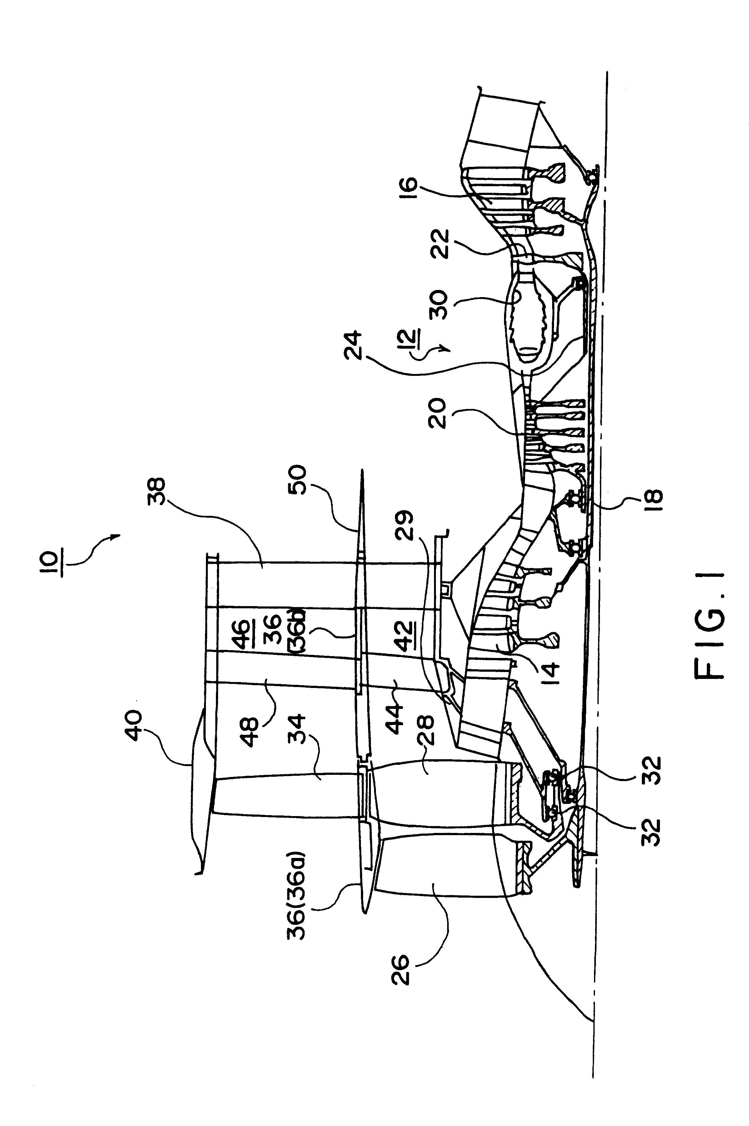
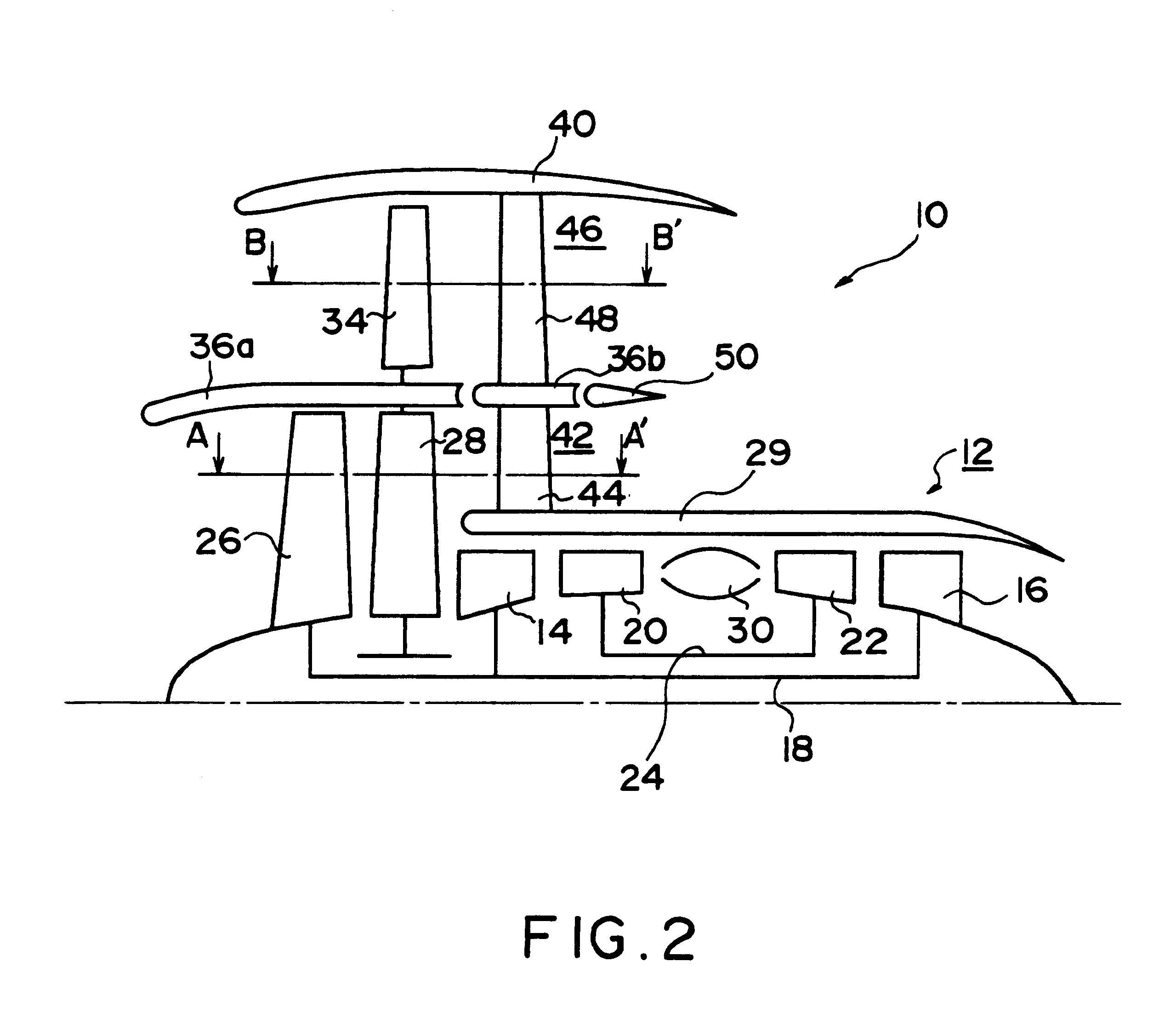
Preferred embodiments of the present invention will next be described with reference to the drawings. FIG. 1 schematically shows the structure of a turbofan engine 20 according to the A core engine 12 of a dual shaft type includes an inner shaft 18 connecting a low-pressure compressor 14 and a low-pressure turbine 16, and an outer shaft 24 connecting a high-pressure compressor 20 and a high-pressure turbine 22. The inner shaft 18 extends upstream and has a forward end connected to an impeller 26. The air channeled downstream by the impeller 26 passes through an air turbine 28, described hereafter, and the air inside a first flow splitter 29 is compressed by the low-pressure and high-pressure compressors 14 and 20 to be directed into a combustion chamber 30. Fuel supplied to the inside of the combustion chamber 30 burns therein and the burnt gas rotates the high-pressure and low-pressure turbines 22 and 16. The gas flowing past the low-pressure turbine 16 is ejected from an exhaust ...

eighth embodiment

FIG. 12 schematically shows the structure of a turbofan engine 710 according to the present invention. In the description of this embodiment as well, components described in connection with the above embodiments are denoted by the same numerals, and their description will not be repeated. According to this embodiment, the fan 734 and a mechanism for transmitting the rotation of the output shaft of the core engine at a reduced speed to a fan 734 are disposed downstream of a core engine 712. The output of the core engine is directed downstream by an inner shaft 718 to drive an impeller 726. The airflow produced by the impeller 726 rotates an air turbine 728, and is channeled through the inner bypass 42 to be ejected downstream. Such ejection flow generates a part of propulsion force. Rotation of the air turbine 728 causes the fan 734 provided integrally at the outside thereof to rotate. The fan 734 produces an airflow in a rearward direction, providing a major part of the propulsion f...

ninth embodiment

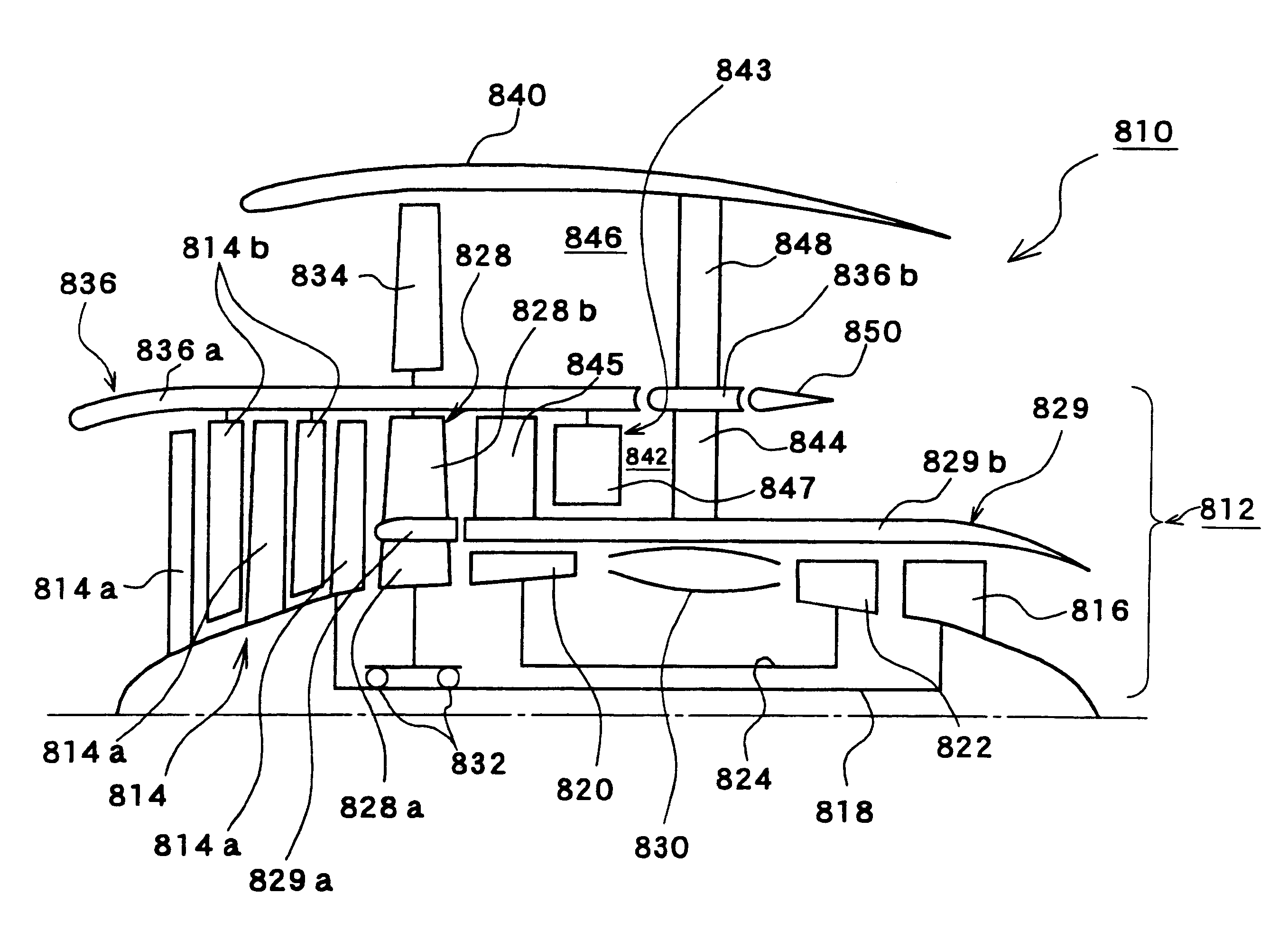
FIG. 13 schematically shows the structure of a turbofan engine 810 according to the present invention. A core engine 812 of a dual shaft type includes an inner shaft 818 connecting a low-pressure compressor 814 and a low-pressure turbine 816, and an outer shaft 824 connecting a high-pressure compressor 820 and a high-pressure turbine 822. An air turbine 828 is provided downstream from the low-pressure compressor 814, and rotated by the airflow produced by the low-pressure compressor 814. The air turbine 828 includes an air turbine splitter 829a for dividing an inner part 828a and an outer part 828b of the air turbine 828. Amain splitter 829b is provided downstream from the air turbine splitter 829a. These two splitters 829a and 829b constitute an inner splitter 829.

The inner part 828a of the air turbine supports the outer part 828b, and has a blade profile that is in line with the airflow discharged from the low-pressure compressor 810 and that does not impede the airflow channeled ...


PUM


Abstract

An impeller is directly driven by an output shaft of a core engine. The airflow produced by the impeller rotates an air turbine and a fan disposed integrally with the air turbine. The impeller and the air turbine form a fluid coupling which serves also as a speed reducing mechanism. The rotational speed of the fan can be reduced to be lower than that of the output shaft while retaining efficiency of the core engine. The outer diameter of the fan can be increased, raising a bypass ratio.

Description

1. Field of the InventionThe present invention relates to turbofan engines commonly used in aircraft travelling at subsonic speeds, and more particularly to a mechanism for reducing fan rotational speed.2. Description of the Related ArtsTurbofan engines have been widely used for aircraft travelling at subsonic speeds. In turbofan engines, propulsive force is gained by an exhaust stream, i.e. a jet, of a core engine in the form of a gas turbine engine and a fan driven by shaft power of the core engine.In such a turbofan engine, the specific fuel consumption can be reduced by increasing the bypass ratio, that is, the ratio of the flow rate of the air directed downstream by the fan but bypassing the core engine to be discharged to the flow rate of air taken into the core engine. That is, higher efficiency can be obtained by increasing the propulsive force by the fan relative to the propulsive force by the jet.A greater bypass ratio can be obtained by increasing the outer diameter of a ...

Claims


Application Information

Patent Timeline
IPC IPC(8): F02C3/00F02K3/065F02K3/068F02K3/077F02K3/075F02C3/13F02C7/36F02C7/00F02K3/00F02K3/04F02K3/06
CPCF02C3/13F02C7/36F02K3/04F02K3/06F02K3/065F02K3/068F02K3/075F02K3/077Y02T50/671Y02T50/60
Inventor ITOH, TAKAHIKOTAKEDA, HIDEO
Owner NIKKISO COMPANY
Why Eureka
Try Eureka