Crossed-drooping bent dipole antenna

a dipole antenna and cross-drooping technology, which is applied in the direction of antennas, electrically short antennas, electrical apparatus, etc., can solve the problems of awkwardly providing an interface for this type of feed arrangement, the height of the antenna (about 15 cm for a typical design at l-band) is too large in the aircraft application, and the difficulty of meeting all of the above requirements

Inactive Publication Date: 2001-04-03
EMS TECH CANADA
View PDF18 Cites 67 Cited by
  • Summary
  • Abstract
  • Description
  • Claims
  • Application Information

AI Technical Summary

Problems solved by technology

It is quite difficult to satisfy all of the above requirements.
However its height (about 15 cm for a typical design at L-band) is too great in the aircraft application.
It would be awkward to provide an interface for this type of feed arrangement, given that the feed circuitry and electronic phase shifters should preferably be incorporated in a strip line device lying just below the elements.
However, such antennae have been very expensive to manufacture.
For microwave frequencie...

Method used


Image

  • Crossed-drooping bent dipole antenna
  • Crossed-drooping bent dipole antenna
  • Crossed-drooping bent dipole antenna

Examples


Embodiment Construction

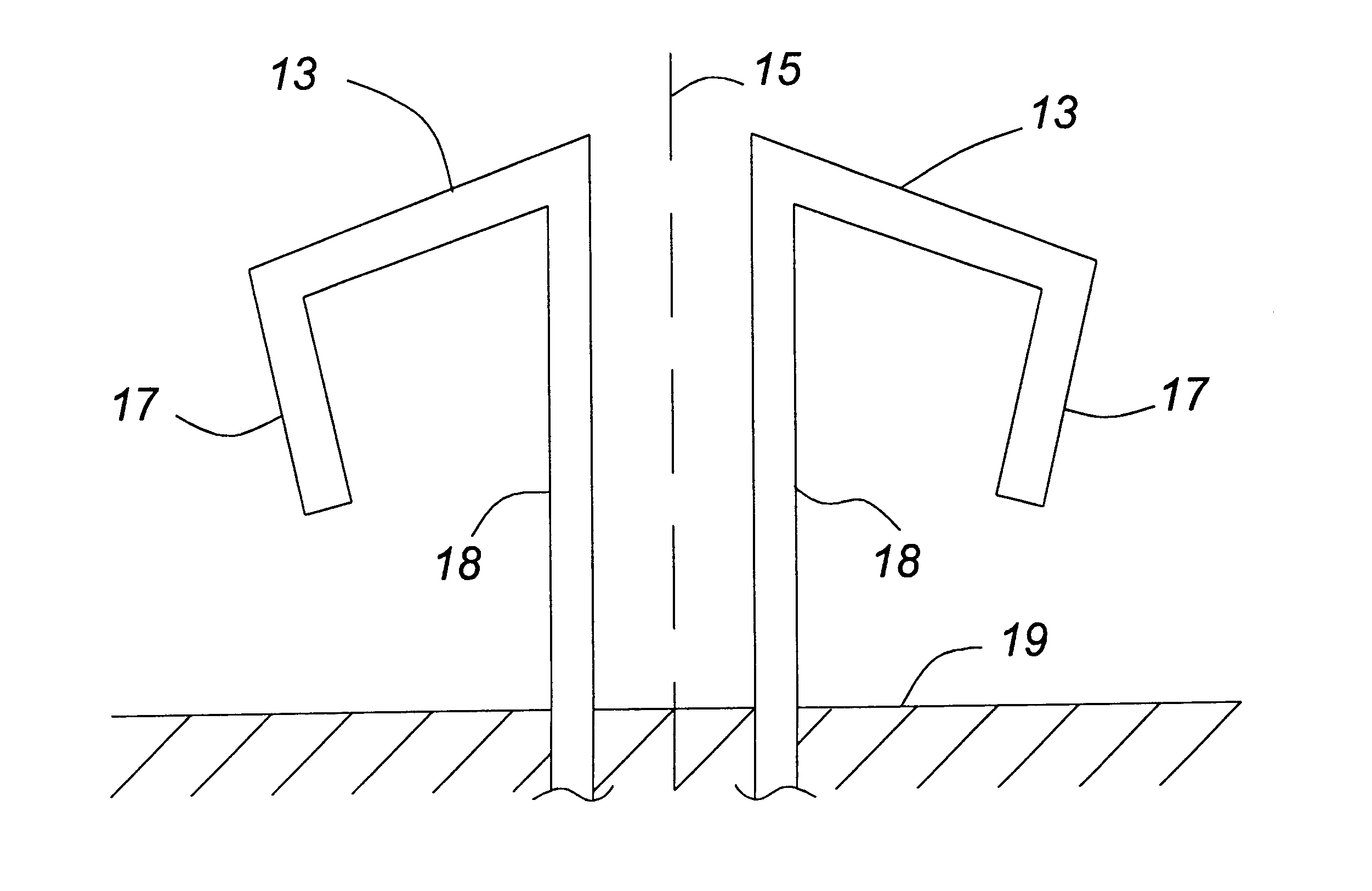
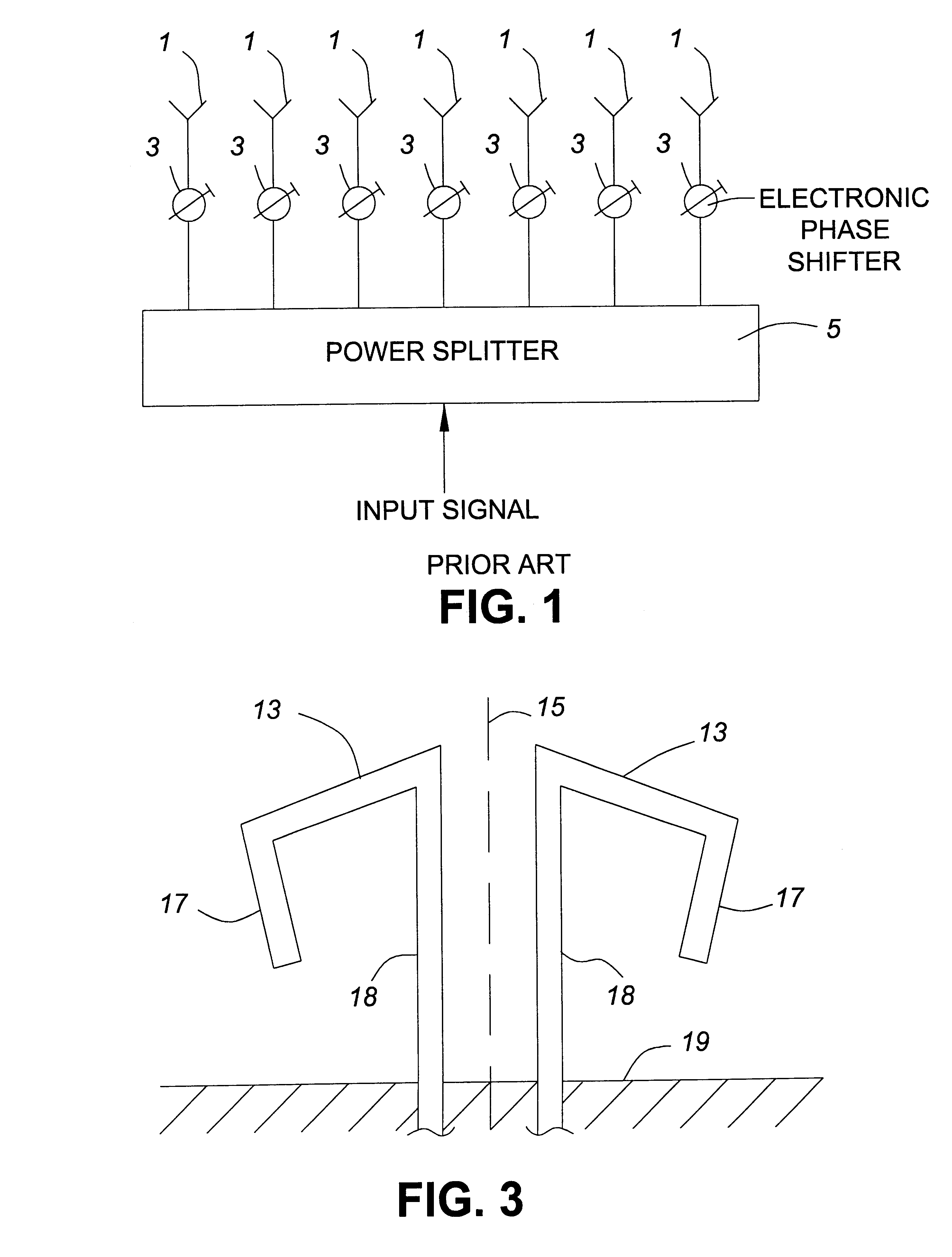
Turning to FIG. 3, the dipole element in accordance with an embodiment of the invention is formed with arms which droop from a central axis 15, end portions 17 of the arms being bent preferably inwardly toward the axis 15. For example, the arms 13 can droop 30.degree. relative to a plane which is orthogonal to axis 15, and the arm portions 17 can be bent downwardly so as to be parallel with the axis 15 or inwardly a fraction of the drooping angle relative to the axis 15. The total length of each monopole 13+17 is typically slightly over, but can be approximately 1 / 4 wavelength in length. The particular angles and arms lengths used will depend on the wavelength to be transmitted or received, the gain and the axial ratio desired over a desired hemisphere, and the height of the arms above the ground plane.

The monopoles are fed at their closest ends by balanced parallel feeder lines 18 which will be described in more detail below. The antenna element, formed of two crossed dipoles, exte...


PUM


Abstract

An antenna comprising at least one dipole, the dipole comprising a pair of arms drooping relative to a plane orthogonal to a central axis, end portions of the arms being bent back toward the central axis. In one form of the invention the arms are bent back toward the central axis in at least one plane which is parallel to the central axis, and in another form of the invention the dipole arms are bent in the same rotational direction out of a pland which includes the central axis.

Description

This invention relates to the field of antennae and in particular to a low profile improved crossed bent dipole antenna which can be used to achieve a wide beam as an isolated element or in a phased array at microwave frequencies.BACKGROUND TO THE INVENTIONIn communications antenna applications, there is sometimes a need to generate an antenna beam which can be scanned electronically to cover a very wide range of pointing angles, the required coverage spanning each of two dimensions. An example is the antenna which forms part of an aircraft electronic system which communicates back to earth via a satellite. The beam of the aircraft antenna must be pointed in the direction of the satellite. However, according to the latitude and longitude location of the aircraft, the line of sight to the satellite may lie at low elevation, that is, very near to the horizon. Alternatively, it may lie directly overhead of the aircraft. Yet again, it may lie at some point between these two extremes. In...

Claims


Application Information

Patent Timeline
IPC IPC(8): H01Q21/26H01Q9/04H01Q9/06H01Q9/26H01Q9/42H01Q21/24
CPCH01Q9/065H01Q9/26H01Q9/42H01Q21/26
Inventor WOOD, PETER JOHNSTRICKLAND, PETER C.FOO, SENGLEEBEST, TIMOTHY EDWARD
Owner EMS TECH CANADA
Why Eureka
Try Eureka