Torsional vibration damper

a torsional vibration and damper technology, applied in the direction of wound springs, couplings, mechanical devices, etc., can solve the problems of insufficient versatility, too large, and expensive, and achieve the effect of convenient and accurate and optimal conformation, convenient design and/or modification, and convenient design

Inactive Publication Date: 2001-04-17
LUK LAMELLEN & KUPPLUNGSBAU BETEILIGUNGS KG
View PDF10 Cites 26 Cited by
  • Summary
  • Abstract
  • Description
  • Claims
  • Application Information

AI Technical Summary

Benefits of technology

A further object of the invention is to provide a torsional vibration damper with one or more energy storing devices which is or are more versatile than heretofore known energy storing devices and which can be put to use under circumstances likely to vary within a wide range, e.g., while a motor vehicle is pulling a load, is idling or is coasting.
An additional object of the invention is to provide a torsional vibration damper with one or more energy storing devices which can be mass produced at a reasonable cost in available machinery and which can be utilized as a superior substitute for presently known energy storing devices.
Still another object of the invention is to provide an energy storing device which can be readily designed and / or modified to be put to optimal use under widely different circumstances.
A further object of the invention is to provide an energy storing device which is constructed and assembled in such a way that its characteristics (particularly its resistance to rotation of the input and output members of a torsional vibration damper relative to each other) can readily and accurately and optimally conform to the circumstances of use of the torsional vibration damper.
Another object of the invention is to provide an energy storing device which can be readily designed to offer different resistances during different stages of rotation of the input and output members of a torsional vibration damper relative to each other.

Problems solved by technology

A drawback of many presently known torsional vibration dampers is that they are too bulky, too expensive and / or insufficiently versatile.
Moreover, the springs (such as coil springs) of energy storing devices in such conventional torsional vibration dampers are not, or cannot be, used to capacity under all circumstances of use which arise in the power train of a motor vehicle or in other fields in which the utilization of one or more torsional vibration damping apparatus is advisable or necessary.

Method used


Image

  • Torsional vibration damper
  • Torsional vibration damper
  • Torsional vibration damper

Examples


Embodiment Construction

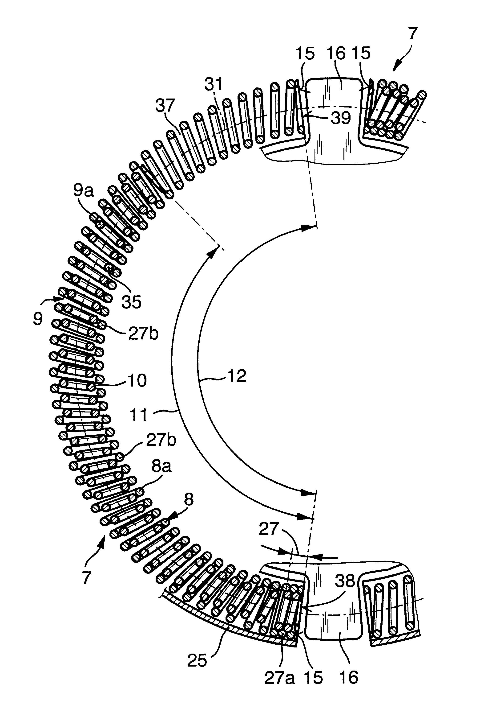
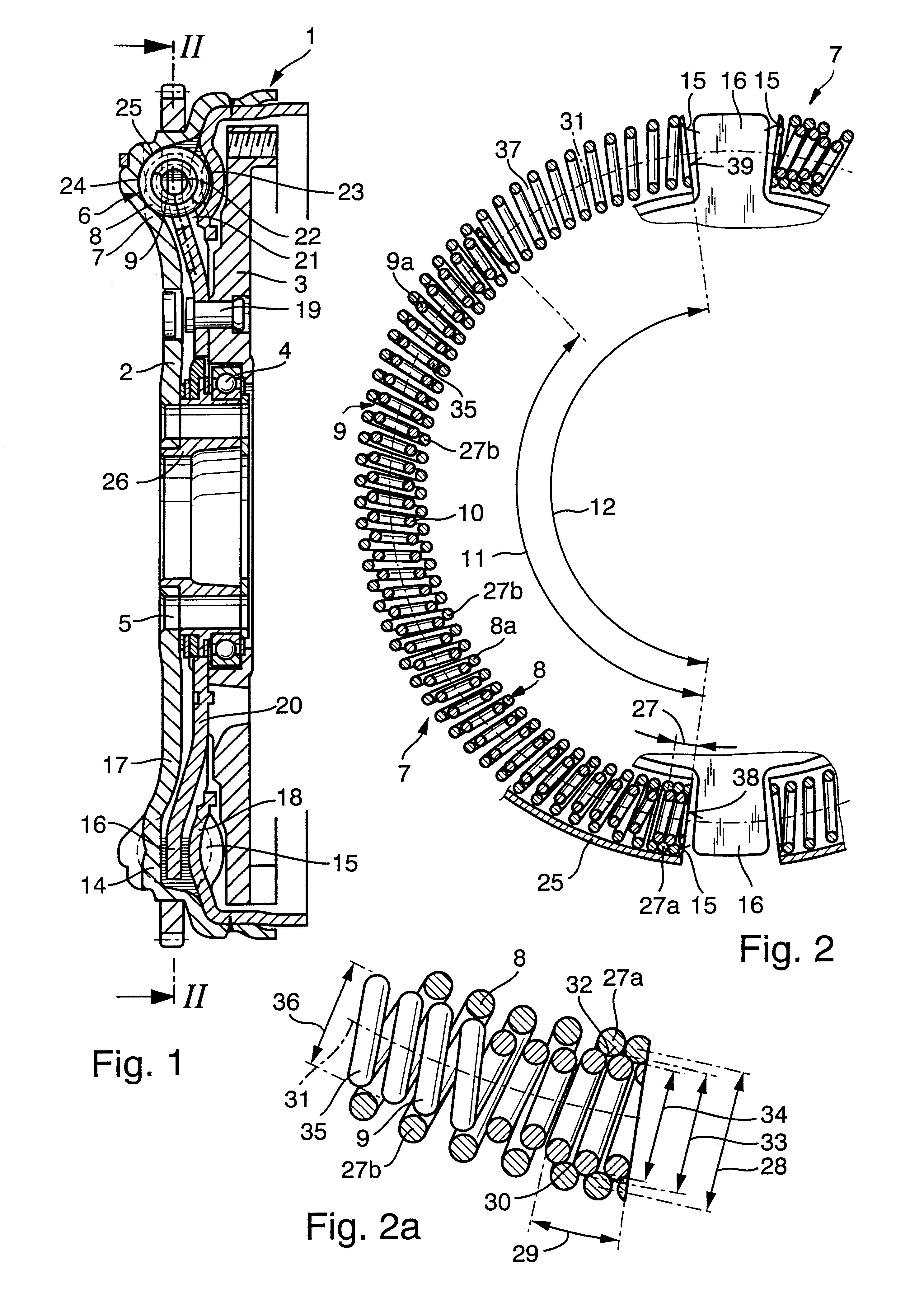
The torsional vibration damper 1 which is shown in FIGS. 1 and 2 constitutes a composite flywheel including a first or primary flywheel 2 adapted to be affixed to the rotary output element of a prime mover in the power train of a motor vehicle, and a second or secondary flywheel 3 which can transmit torque to the housing of a friction clutch. When engaged, the clutch can transmit torque to the rotary input element of a change speed transmission in the power train of the motor vehicle. Reference may be had, for example, to commonly owned U.S. Pat. No. 5,456,634 (granted Oct. 10, 1995 to Paul Maucher et al. for "TORSION DAMPING APPARATUS FOR USE WITH FRICTION CLUTCHES IN THE POWER TRAINS OF MOTOR VEHICLES") which shows the manner in which a torsional vibration damper can be installed between the crankshaft or camshaft of a combustion engine and the housing of a friction clutch serving to transmit torque to the input shaft of a transmission.

A ball bearing 4 is installed between the fly...


PUM


Abstract

The coil springs of an arcuate energy storing device in a torsional vibration damper are fitted into each other in such a way that at least one convolution of the inner spring engages at least one convolution of the outer spring when the energy storing device is caused to store energy (or to store additional energy) and / or is permitted to dissipate energy while the damper is in actual use, e.g., between the primary and secondary flywheels of a composite flywheel in the power train of a motor vehicle. The at least one convolution of the outer spring can be facetted and / or deformed for reliable engagement with the at least one convolution of the inner spring, and the at least one convolution of the inner spring can have a circular or a non-circular outline. The at least one convolution of the inner spring can engage one or more end convolutions or one or more intermediate convolutions of the outer spring.

Description

The present invention relates to dampers in general, and more particularly to improvements in torsional vibration dampers which can be utilized in the power trains of motor vehicles, for example, to at least partially absorb shocks between the rotary output element of a prime mover (such as the camshaft or crankshaft of an internal combustion engine) and the housing of a friction clutch which is engageable to transmit torque to the rotary input element of a change-speed transmission. Still more particularly, the invention relates to improvements in torsional vibration dampers wherein an input member and an output member are rotatable with each other about a common axis as well as relative to each other against the opposition of one or more energy storing devices.Commonly owned U.S. Pat. No. 5,377,796 (granted Jan. 3, 1995 to Oswald Friedmann et al. for "APPARATUS FOR TRANSMITTING FORCE BETWEEN ROTARY DRIVING AND DRIVEN UNITS") discloses a hydrokinetic torque converter wherein a tors...

Claims


Application Information

Patent Timeline
Patent Type & Authority Patents(United States)
IPC IPC(8): F16F15/134F16F15/131F16F1/12F16F1/04F16F3/06F16F15/16F16F15/30
CPCF16F1/123F16F3/06F16F15/13461
Inventor KOOY, ADMENDE, HARTMUTJACKEL, JOHANNRAIMANN, ANDREAS
Owner LUK LAMELLEN & KUPPLUNGSBAU BETEILIGUNGS KG
Why Eureka
Try Eureka