Irradiation dose calculation unit, irradiation dose calculation method and recording medium

a technology of irradiation dose and calculation method, which is applied in the field of irradiation dose calculation unit, irradiation dose calculation method and recording medium, can solve the problems of not always ensuring the optimum dose to the target and the critical organs

Inactive Publication Date: 2001-04-24
MITSUBISHI ELECTRIC CORP
View PDF3 Cites 85 Cited by
  • Summary
  • Abstract
  • Description
  • Claims
  • Application Information

AI Technical Summary

Problems solved by technology

This method, however, presents a problem in that optimum dos

Method used


Image

  • Irradiation dose calculation unit, irradiation dose calculation method and recording medium
  • Irradiation dose calculation unit, irradiation dose calculation method and recording medium
  • Irradiation dose calculation unit, irradiation dose calculation method and recording medium

Examples


embodiment 1

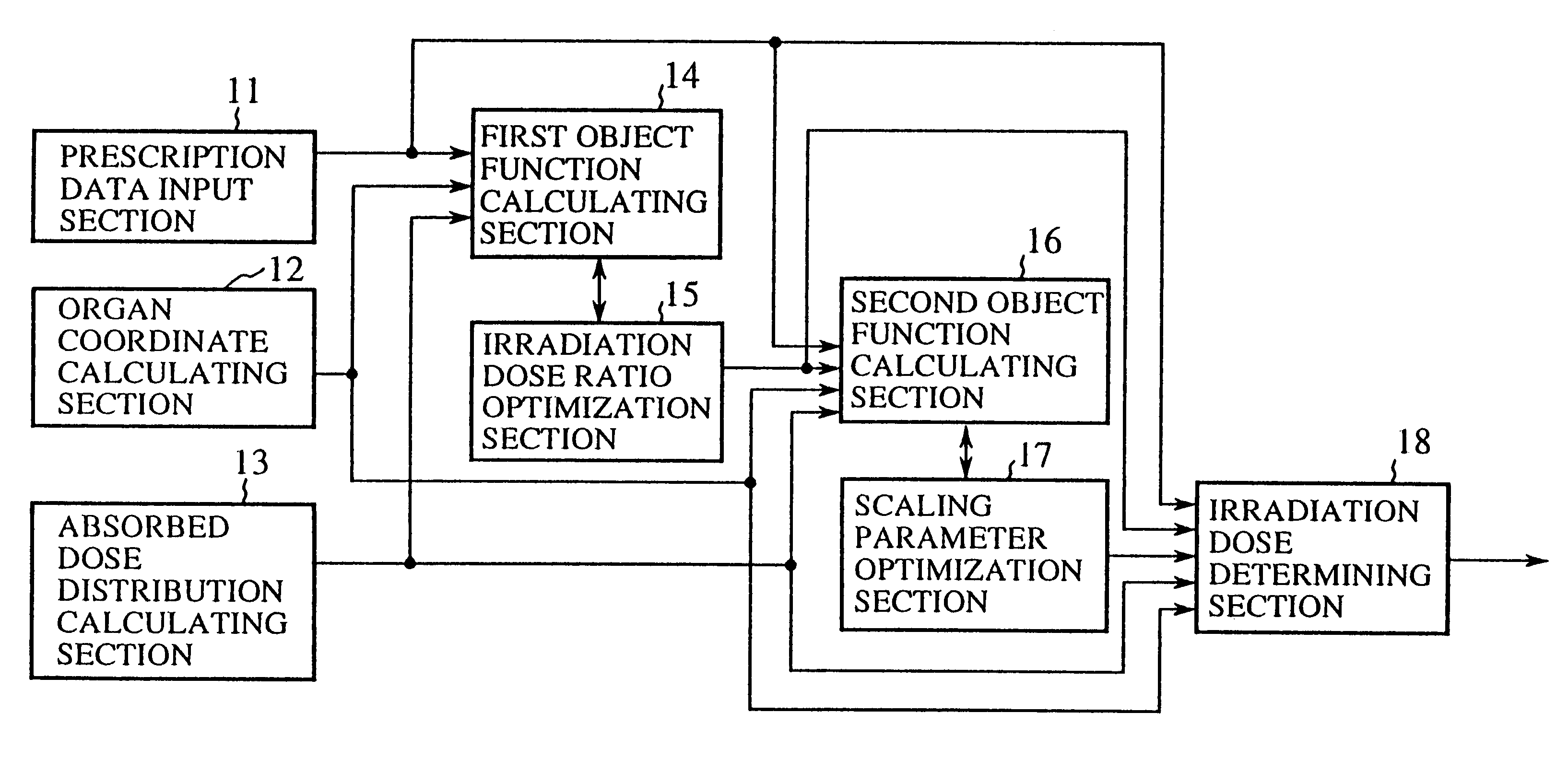
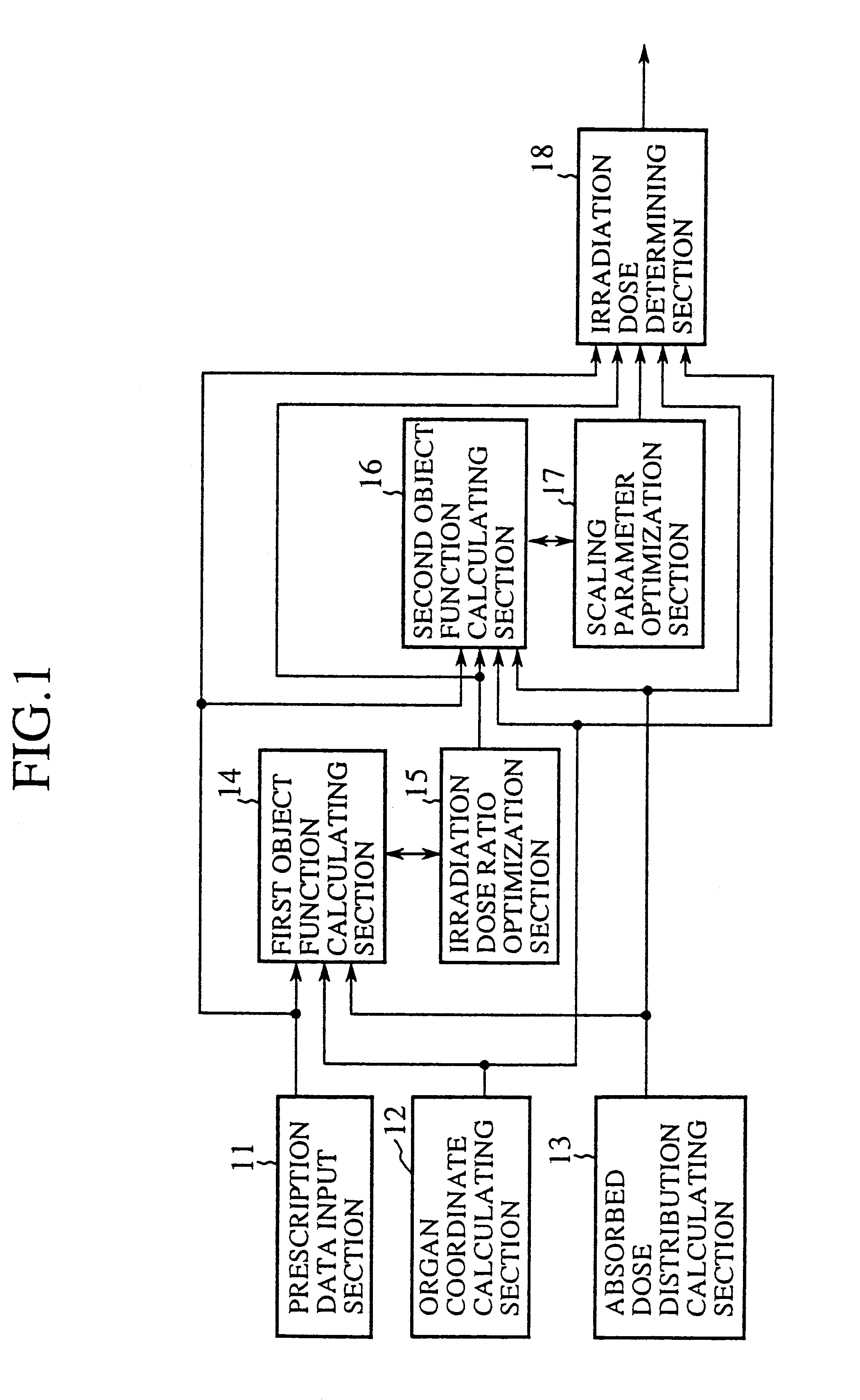
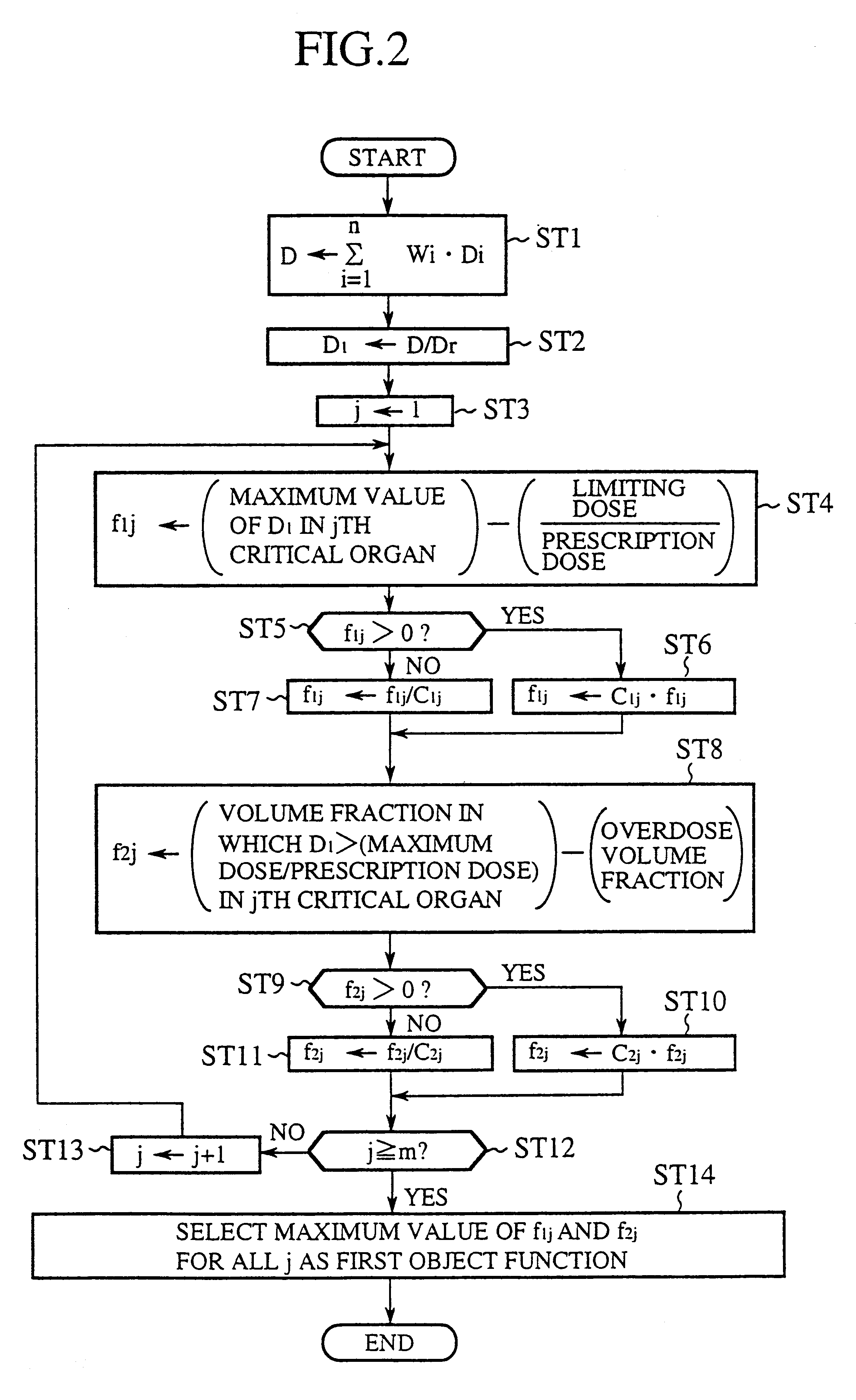
FIG. 1 is a block diagram showing an irradiation dose calculation unit in accordance with the present invention. In FIG. 1, the reference numeral 11 designates a prescription data input section for a physician to input prescription data. The prescription data includes reference coordinates, a prescription dose, a maximum dose, a minimum dose, and an underdose volume fraction of each target; a limiting dose, a maximum dose and an overdose volume fraction of each critical organ; and constraint weights indicative of the importance of individual targets and critical organs. Here, the underdose volume fraction is the upper limit of the volume fraction of the target that is exposed to irradiation less than the minimum dose, and the overdose volume fraction is the upper limit of the volume fraction of the critical organ that is exposed to irradiation greater than the maximum dose. The reference numeral 12 designates an organ coordinate calculating section for calculating from image data th...

embodiment 2

Although the embodiment 1 employs the iterative search method for optimizing the irradiation dose ratios when calculating the first object function, the present embodiment 2 employs a simulated annealing method or a gradient method like a conjugate gradient method instead of the iterative search method to optimize the irradiation dose ratios. It is also possible to begin the optimization with the simulated annealing method, and to change it to the conjugate gradient method in midstream of the optimization. The simulated annealing method and the gradient method like the conjugate gradient method are described in W. H. Press, et al., "Numerical Recipes in FORTRAN", second edition, Cambridge university press, 1992.

Thus, the present embodiment 2 optimizes the irradiation dose ratios using the simulated annealing method and the gradient method like the conjugate gradient method. This offers an advantage of being able to optimize the irradiation dose ratios efficiently.

embodiment 3

Although the embodiment 1 calculates the first and second object functions on the basis of the first to fifth indices, other indices are also available. Among them are indices multiplied by a penalty coefficient that increases when the dose uniformity or dose prescription condition in the target is not satisfied, and indices obtained by the volume integral of the doses for the critical organs. Furthermore, although the embodiment 1 adopts the maximum values of the indices as the first and second object functions, the total sum of the indices can be used as the first and second object functions.

According to the embodiment 3, an advantage like that of the embodiment 1 can be achieved by using other indices.


PUM


Abstract

An irradiation dose calculating unit can solve a problem of a conventional irradiation dose calculating unit in that since irradiation doses from portals are empirically determined, it is likely that optimum irradiation doses are not established for a target and a critical organ. A prescription data input section is used for a physician to input prescription data designating doses to a target and a critical organ. First and second object function calculating sections each calculate predefined indices, and obtain a first object function representing the level of satisfaction for the critical organ and a second object function representing the level of satisfaction for the target and critical organ. The irradiation doses from the portals are calculated based on these object functions such that the prescription data are satisfied.

Description

1. Field of the InventionThe present invention relates to an irradiation dose calculation unit and an irradiation dose calculation method for calculating from prescription data irradiation doses from one or more portals (directions) to a target, and to a recording medium for recording a program for implementing the irradiation dose calculation method.2. Description of Related ArtFIG. 18 is a view illustrating proton beam radiation therapy described in M. Urie, "Treatment Planning for Proton Beams", Ion Beams in Tumor Therapy published by CHAPMAN & HALL, pp. 279-289, 1995. In this figure, the reference numeral 1 designates a CT (Computed Tomography) of the head of a subject; 2 designates a target tumor for proton beam radiation; 3 designates a brain stem as a critical organ fragile to radiation; 4 designates a proton beam; 6 designates a bolus for varying the dose distribution in depth direction so as to focus a high dose portion on the location of the tumor 2; and 7a and 7b designat...

Claims


Application Information

Patent Timeline
IPC IPC(8): A61N5/10A61B6/03G06Q50/22
CPCA61N5/1031
Inventor YODA, KIYOSHIKANEMATSU, NOBUYUKI
Owner MITSUBISHI ELECTRIC CORP
Why Eureka
Try Eureka