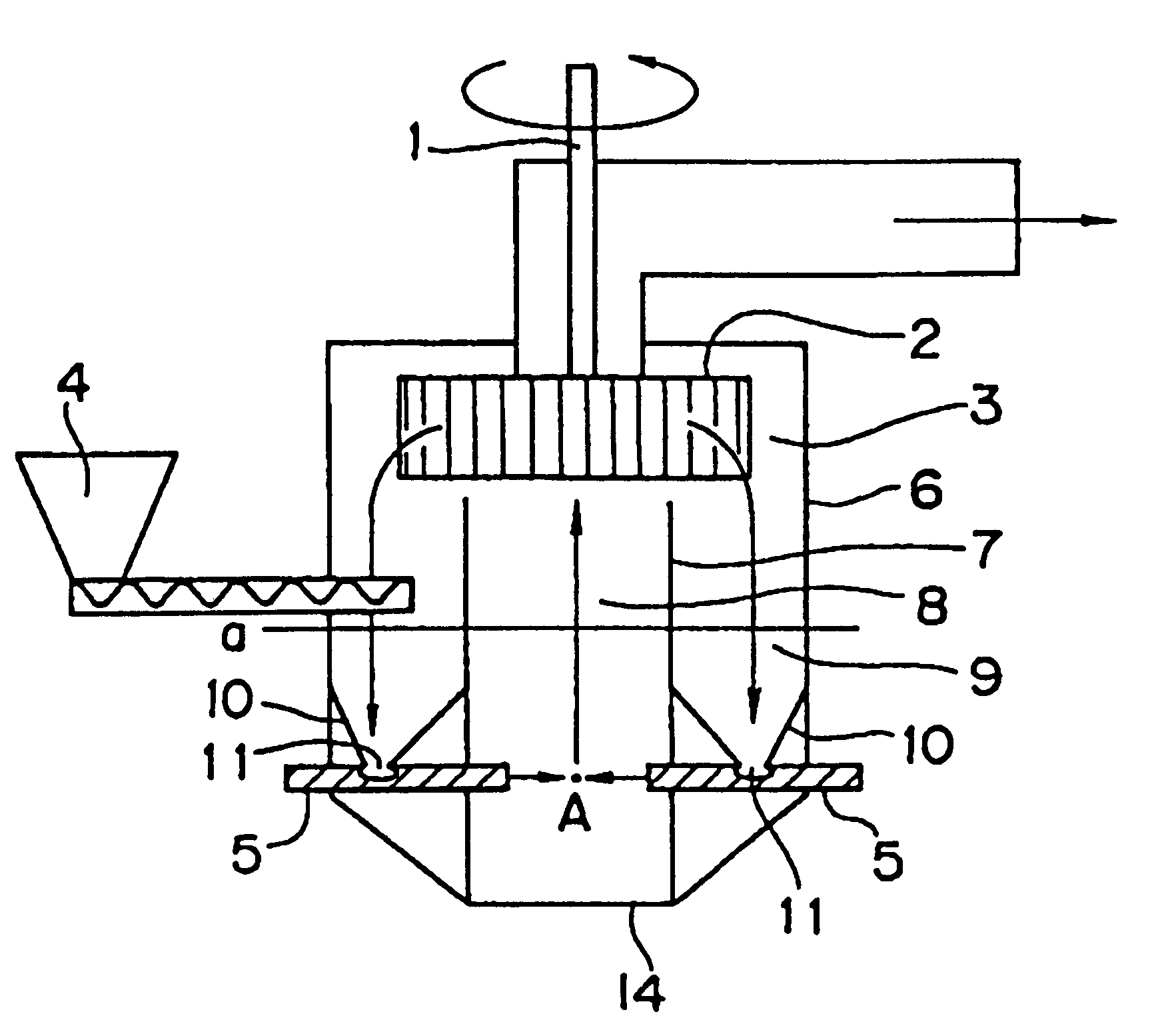
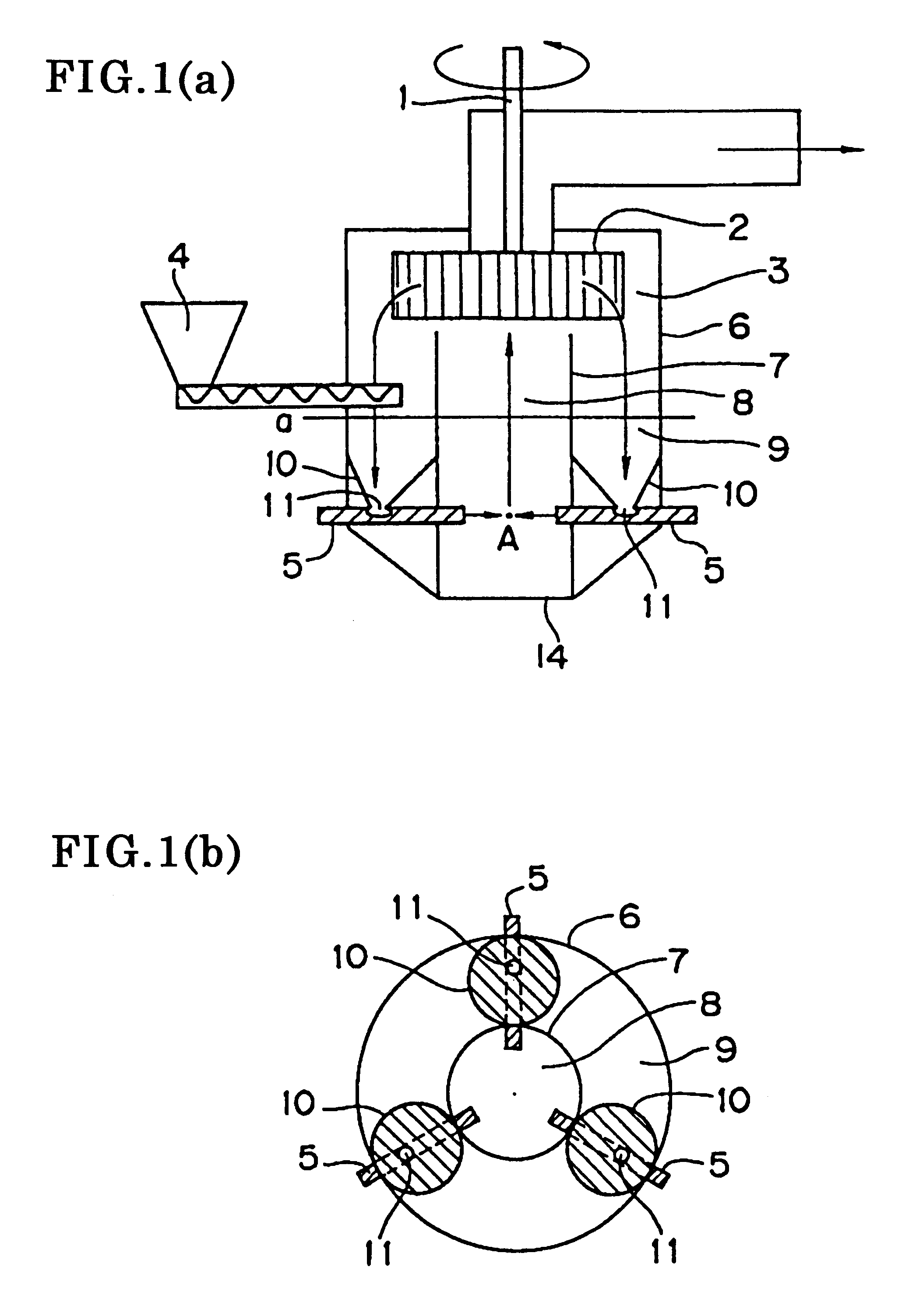
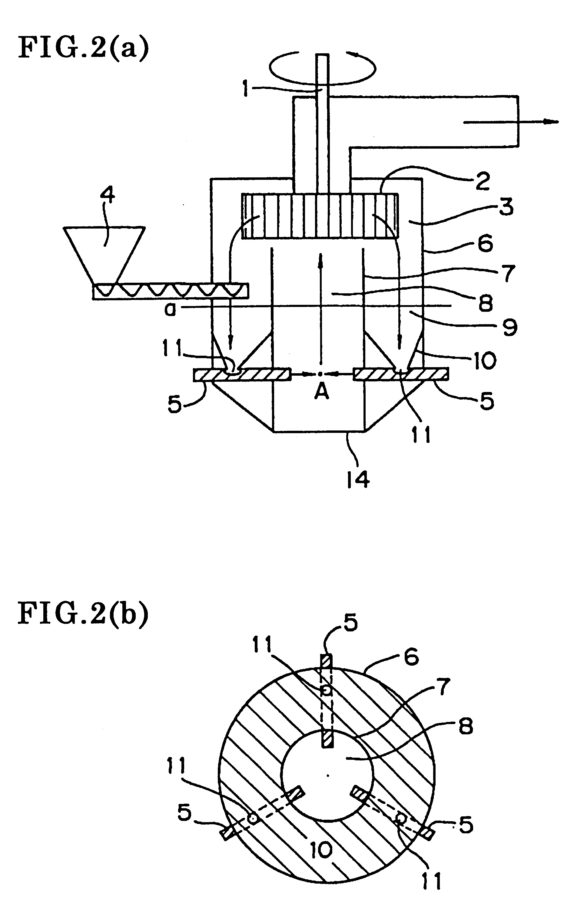
Mill provided with partition within milling chamber
a milling chamber and milling technology, applied in the field of mills, can solve the problems of poor milling efficiency (milling capacity per unit time) of the conventional mill described above, and achieve the effect of facilitating manufacturing and substantially reducing manufacturing costs
- Summary
- Abstract
- Description
- Claims
- Application Information
AI Technical Summary
Benefits of technology
Problems solved by technology
Method used
Image
Examples
second example
Other than that the mill shown in FIGS. 3(a) and 3(b) was used, a milled material having a volume average particle diameter of 8.0 .mu.m was obtained based on a feed amount of 12.0 kg / h in the same manner as in the first example. The milling conditions used are shown below. The classification conditions used were the same as in the first example.
Milling conditions
Separating plate: Of a cylindrical configuration; inner diameter of the horizontal cross-section of the separating plate: 250 mm; connecting openings present at the bottom (diameter 10 mm, 40 openings at equal distances); space between the classifier and the top edge of the separating plate: 2.5 mm.
Collision member: Of an equilateral triangular pyramid configuration; angle between the nozzle axes and the collision member surface: 45 degrees; stainless steel
Nozzles: Three nozzles (horizontally located in equidistant fashion); inner diameter: 5 mm, compressed air pressure: 6 kg / cm.sup.2 ; distance from nozzle tip to collision...
third example
Other than that the mill shown in FIGS. 4(a) and 4(b) was used, a milled material having a volume average particle diameter of 8.0 .mu.m was obtained based on a feed amount of 10.0 kg / h in the same manner as in the first example. The milling conditions used are shown below. The classification conditions used were the same as in the first example.
Milling conditions
Separating plate: Of a cylindrical configuration; inner diameter of the horizontal cross-section of the separating plate: 250 mm; space between the classifier and the top edge of the separating plate: 2.5 mm. (The separating plate has arch-shaped openings to secure paths for the flow of the high-velocity gas from the nozzles. Connection openings (having a diameter of 10 mm) are formed in equidistant fashion at the bottom of the separating plate that is connected to the base.)
Collision member: flat plate; angle between the nozzle axes and the collision member surfaces: 45 degrees; stainless steel Nozzles: Two nozzles (horizo...
fourth example
Other than that the mill shown in FIGS. 5(a) and 5(b) was used, a milled material having a volume average particle diameter of 8.0 .mu.m was obtained based on a feed amount of 12.0 kg / h in the same manner as in the first example. The milling conditions used are shown below. The classification conditions used were the same as in the first example.
Milling conditions
Separating plate: Of a cylindrical configuration; inner diameter of the horizontal cross-section of the separating plate: 250 mm; space between the classifier and the top edge of the separating plate: 2.5 mm. (The separating plate has arch-shaped openings to secure paths for the flow of the high velocity gas from the nozzles. Connection openings (having a diameter of 10 mm) are formed in equidistant fashion at the bottom of the separating plate that is connected to the base.)
Collision members: flat plates; angle between nozzle axes and collision member surfaces: 45 degrees; stainless steel
Nozzles: Two nozzles (horizontally ...
PUM
 Abstract
Description
Claims
Application Information
 - R&D
- Intellectual Property
- Life Sciences
- Materials
- Tech Scout
- Unparalleled Data Quality
- Higher Quality Content
- 60% Fewer Hallucinations
Browse by: Latest US Patents, China's latest patents, Technical Efficacy Thesaurus, Application Domain, Technology Topic, Popular Technical Reports.
© 2025 PatSnap. All rights reserved.Legal|Privacy policy|Modern Slavery Act Transparency Statement|Sitemap|About US| Contact US: help@patsnap.com


