Modular display system

a display system and module technology, applied in the field of display systems, can solve the problems of lack of integrated electrical wiring, heavy weight of partition wall systems, and inability to meet the requirements of display systems that are presently available, and achieve the effect of convenient accurate positioning and alignment of sheet material displays, and compact storag

Inactive Publication Date: 2001-05-08
CANFIELD INDS
View PDF13 Cites 39 Cited by
  • Summary
  • Abstract
  • Description
  • Claims
  • Application Information

AI Technical Summary

Benefits of technology

The design of the invention allows extremely compact storage as the vertical elements are all elongated structures which may be laid on their sides parallel to the elongated base units for storage and transportation. The design also facilitates accurate positioning and alignment of sheet material displays. The bottom of the sheet is attached to an overlay base tab which accurately defines the lower edge of the sheet material for alignment with the base

Problems solved by technology

Display systems that are presently available fail to meet many of these requirements.
Partition wall systems tend to be heavy and difficult to adjust during assembly because the entire partition wall must be moved or repositioned each time a change is desired.
Another difficulty with partition wall systems is the lack of integrated electrical wiring.
Consequently, electrical cables and any specialized communication or control cables must be strung after the display is set up, and the cables become a tripping hazard.
Another difficulty with partition walls systems is that some designs do not accom

Method used


Image

  • Modular display system
  • Modular display system
  • Modular display system

Examples


Embodiment Construction

)

In describing the preferred embodiment of the present invention, reference will be made herein to FIGS. 1-9 of the drawings in which like numerals refer to like features of the invention.

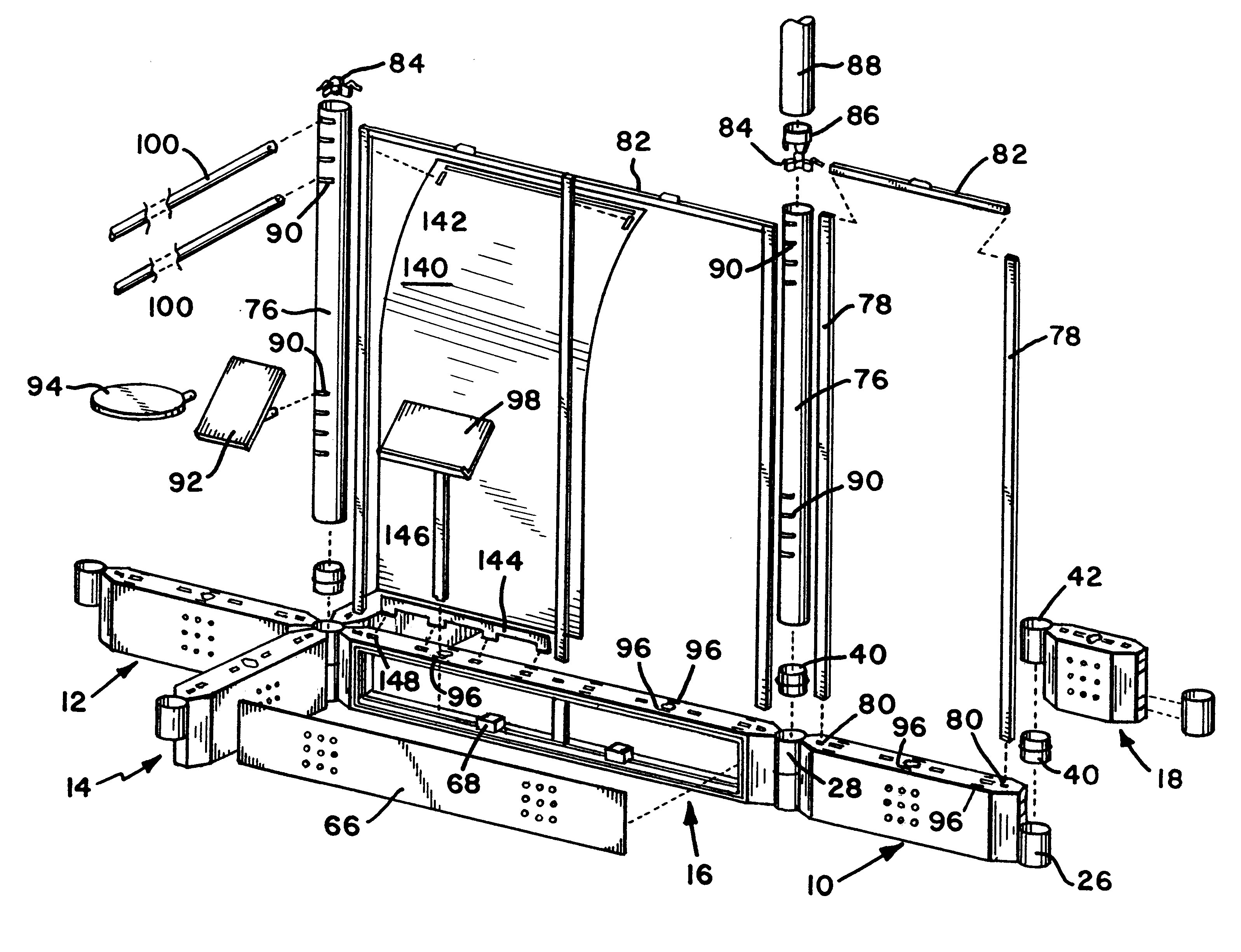
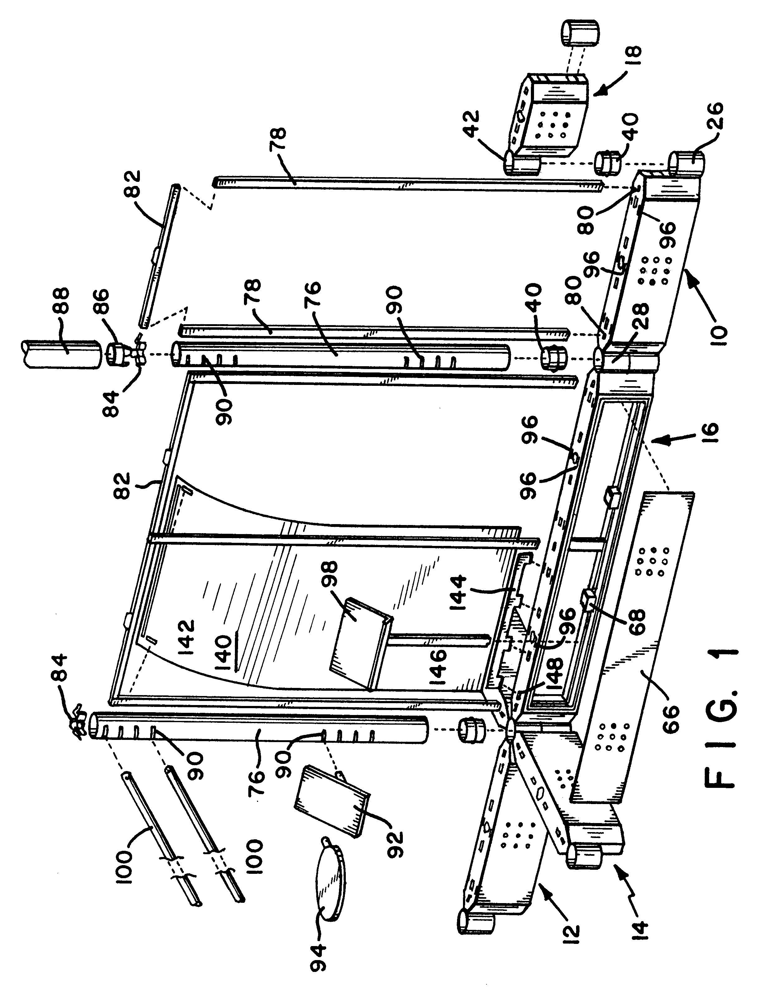
Referring to FIGS. 1 and 4, the present invention includes base units 10, 12, 14, 16, 18 connected together to form part of the lower perimeter outline of a display area. Additional base units of the same types will generally be used to complete the display area. The display may be generally linear, and positioned along a wall, or more often, will form an island type booth viewable from all sides.

Referring to FIG. 4, a basic single base unit 10 includes a body 20 having angled ends 22, 24 that are adapted to receive detachable end members 26, 28. The end members preferably comprise cylindrical column collars of the type shown. Alternative shapes for the end members are various types of regular polygons including; hexagons, octagons and the like which permit the end members to be engaged at differen...


PUM


Abstract

A modular display system includes base units angularly positionable relative to one another on a floor area to define a lower edge of a display space. Base units include an elongated body and a pair of detachable end members connectable to the opposed ends of the elongated body at upper or lower positions. An end member connected at a lower position at one end of the body is connectable at a plurality of angles to an end member on an adjacent base unit connected at the upper position. The angular connection allows the display area to be defined and adjusted prior to installation of vertical elements forming walls. Vertical supports, preferably including columns positioned over the end members between the base units and uprights supported in sleeves in the base units are removably connectable to the base units. Crossbars are removably connectable to the upper ends of the vertical supports for defining an upper edge of the display space. Sheet material displays are positionable on the base units, vertical supports and crossbars to define walls. Electrical outlets are integrated into the system and attachment points for display accessories and shelves are provided.

Description

1. Field of the InventionThis invention relates to display systems of the type commonly used at trade shows, conventions and in public areas to display goods or offer services for sale and which define a display area and separate it from the display areas of other vendors.2. Description of Related ArtTrade shows and conventions have become an important avenue for introducing new products and services to potential customers. Vendors have a need for a reliable display system that can be quickly assembled and disassembled to establish a display area. The display system must be easily transportable between display locations, must be structurally sound, self supporting and adaptable to produce differently shaped display areas to accommodate varying requirements at different exhibition venues.It is highly desirable for the display system to define the display area as a booth or enclosure with walls providing vertical display areas on the inside and outside wall surfaces. The walls must pr...

Claims


Application Information

Patent Timeline
IPC IPC(8): A47F5/10E04B2/74
CPCA47F5/106E04B2/7438E04B2002/7468E04B2002/7483E04B2002/7487E04B2002/7488
Inventor HAVERSAT, MARK A.
Owner CANFIELD INDS
Why Eureka
Try Eureka