Brush seal

Inactive Publication Date: 2001-05-15
EATON CORP +2
View PDF38 Cites 39 Cited by
  • Summary
  • Abstract
  • Description
  • Claims
  • Application Information

AI Technical Summary

Benefits of technology

It is a further object of this invention to provide such an improved brush seal which is simpler and less expensive.
It is a further object of this invention to provide such an improved brush sea

Problems solved by technology

This makes the bristles non-parallel and makes their pack density (number of bristles per in.sup.2) non-uniform; this introduces a number of problems.
Since the bristles are not uniformly distributed there is inconsistent wear and inconsistent leakage with resulting reduced life and performance.
The non-uniform density produces weak spots where the fluid being sealed may tunnel through and cause leakage.
Bristle blow down can occur where air or other fluid tu

Method used


Image

  • Brush seal
  • Brush seal
  • Brush seal

Examples


Embodiment Construction

Other objects, features and advantages will occur to those skilled in the art from the following description of a preferred embodiment and the accompanying drawings, in which:

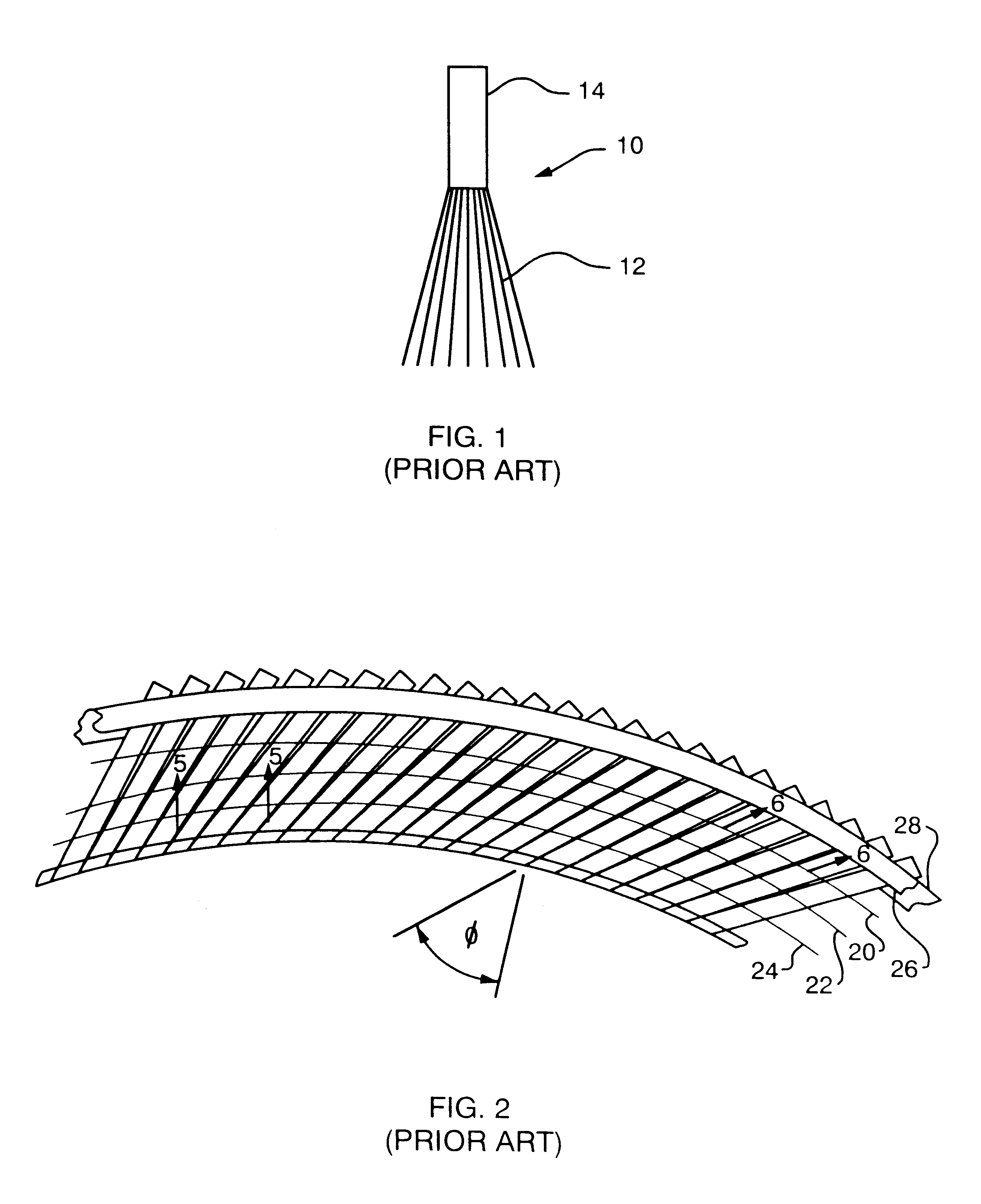
FIG. 1 is a diagrammatic side elevational view of a tuft of bristles in accordance with the prior art;

FIG. 2 is a side elevational schematic diagram showing the installation of a number of tufts such as shown in FIG. 1 with a retainer;

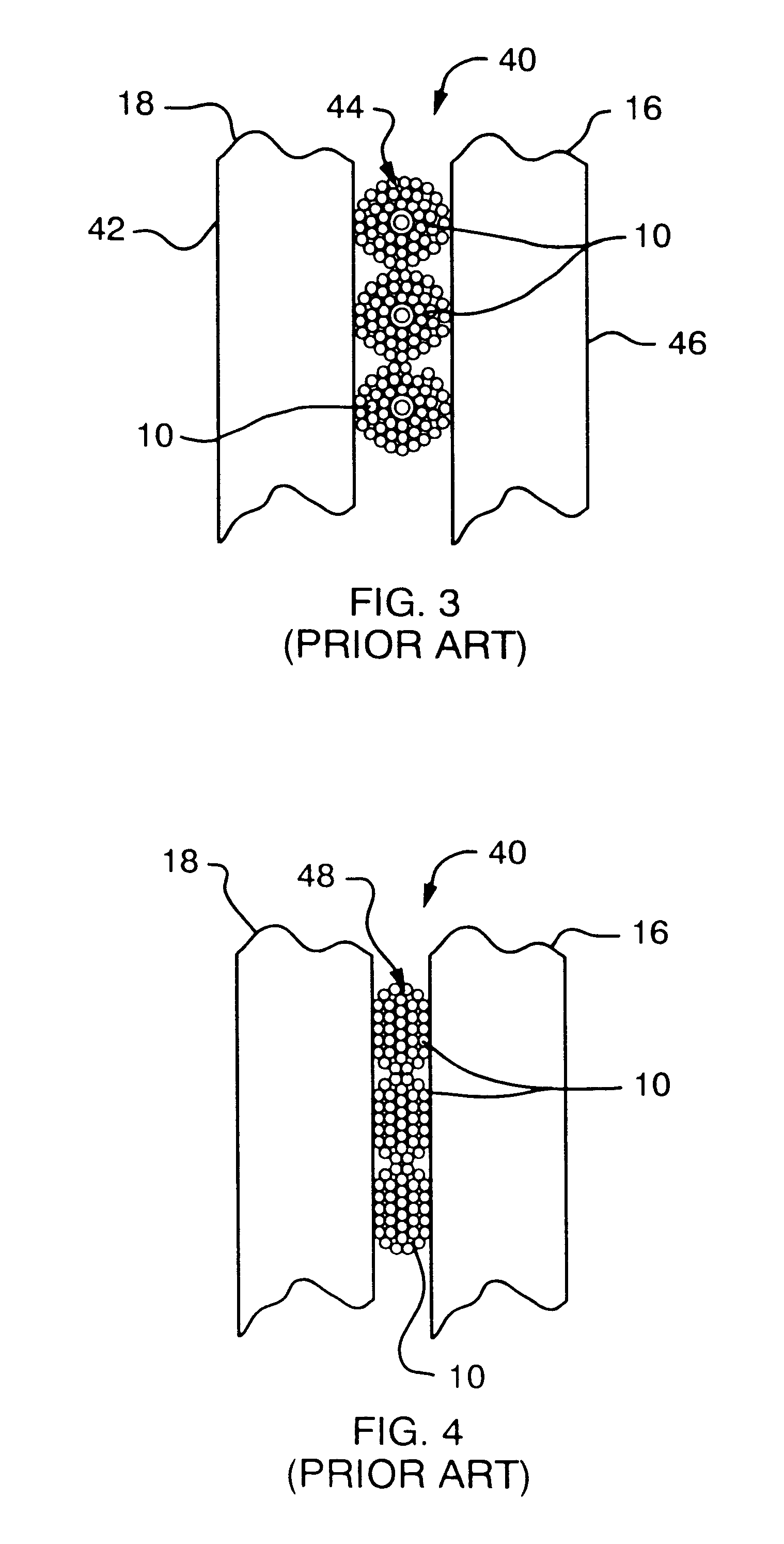
FIG. 3 is a sectional view taken along line 3--3 of FIG. 2 showing the circular shape of the tufts before they are squeezed between a pair of curved retaining elements;

FIG. 4 is a view similar to FIG. 3 showing the tufts after they are compressed between a pair of retaining elements;

FIGS. 5 and 6 are views taken along lines 5--5 and 6--6 of FIG. 2 showing the non-uniform pack density of the prior art tufts;

FIG. 7 is a side elevational view of a prior art linear brush seal showing the spreading non-uniform pack density;

FIG. 8 is a cross-sectional view taken along line 8--8 of FIG. ...


PUM


Abstract

A brush seal includes a retainer and a multiplicity of single bristles each bristle having a fixed end and a free sealing end, the fixed ends being individually attached in a continuous arrangement at the same angle to the retainer, the bristles having a uniform pack density throughout the extent of the bristles from the fixed to the sealing end.

Description

This invention relates to an improved brush seal, and more particularly to such a brush seal which has uniform pack density throughout the extent of the bristles.BACKGROUND OF INVENTIONPresently there are a number of techniques for making a brush seal using a plurality of tufts of bristles. In one technique the bristles are gathered at one end into a tuft; the tufted end of a plurality of such tufts are embedded in series in an epoxy retainer or rail. The rail is bent into an annular shape with the unattached ends of the tufts extending radially outwardly and across a back plate. A front plate is attached with unattached ends of the tufts sandwiched between the plates. The unattached ends of the bristles are trimmed and attached as by welding at the O.D. of the back plate and become the fixed ends of the bristles in the seal while the tufted ends of the bristles are trimmed off beyond the I.D. and become the free sealing ends of the bristles which ride on a shaft for example. The tu...

Claims


Application Information

Patent Timeline
IPC IPC(8): F16J15/32
CPCF16J15/3288
Inventor CUNNINGHAM, MATTHEW D.MENENDEZ, ROBERT P.HENDERSON, JAMES A.SHIA, CHIH-YUANCASEY, WILLIAM J.SMITH, JR., WILLIAM W.
Owner EATON CORP
Why Eureka
Try Eureka