Electrical household appliance system

a technology for electrical household appliances and circuits, applied in the integration of power network operation systems, ac network voltage adjustment, sustainable buildings, etc., can solve the problems of increasing the cost affecting the service life of electrical household appliances, so as to achieve the effect of entail additional costs

Inactive Publication Date: 2015-08-06
WHIRLPOOL CORP
View PDF2 Cites 7 Cited by
  • Summary
  • Abstract
  • Description
  • Claims
  • Application Information

AI Technical Summary

Benefits of technology

[0020]The communication system provided according to the aforesaid embodiment of the invention differs sharply from communication systems on known powerlines, because it does not require any specific transmission device, but uses the same electronic means already present both on the electrical household appliance and on the control device, and consequently does not entail additional costs on the aforesaid devi

Problems solved by technology

In the first case (case a) there exists the problem of the cost of the communication node, which renders the corresponding products less competitive, and the problem of tying down the electrical appliance to a given communication technology that is liable to undergo over time frequent modifications and updates, which result in non-negligible maintenance costs that tend to put the brake on the development of electrical household appliances of a smart-grid-ready type, i.e., natively prearranged for interacting with the latest-generation electrical grids (smart grids).
This method presents the advantage of proposing a mode of transmission of information from the electrical household appliance to the outside world that is extremely inexpensive and effective, but also presents the defect of requiring, at the level of external control device, a circuitry for t

Method used


Image

  • Electrical household appliance system
  • Electrical household appliance system
  • Electrical household appliance system

Examples


case b

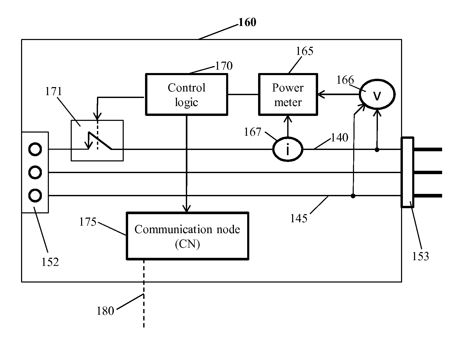
[0054] information regarding the current operating status (status) of the electrical household appliance, useful for example for informing the user on the state of advance of a given program (washing program, if it is a washing machine or a dish-washer, or else cooking program, etc.) through the communication means of a home-automation system connected to the local network 180 that sees the electrical household appliance itself as a peripheral device associated to its system;

case c

[0055] information regarding an interaction event (event) with the electrical household appliance by the user, the aforesaid information being useful, for example, in the case where a telemedicine system that uses the electrical household appliances as source of information on the daily behaviour of an infirm user who needs assistance is connected to the local network 180;

case d

[0056] a statistical datum (statistic) regarding the work cycles performed by the electrical household appliance or other information deemed useful by the manufacturer of the electrical household appliance itself;

[0057]Case e. a diagnostic code (diagnostic) processed by the system of self-diagnosis of the electrical household appliance, useful for remote assistance of the product;


PUM


Abstract

A control device for an electrical appliance operatively set between an electrical supply line of the electrical appliance and a corresponding alternating current (AC) voltage supply source, the control device having a digital control system that encodes information via controlled interruptions of the AC voltage of supply of the electrical appliance and has a first controllable switch managing in an ON-OFF mode the AC voltage from the supply source to the electrical appliance, wherein the encoding comprises carrying out a coding of information as sequences of interruptions having fixed duration of the AC voltage of supply of the electrical appliance, said interruptions having fixed duration being separated by a corresponding interval having variable duration, wherein the information to be transmitted is associated to the variable duration of the interval and the fixed duration of the interruptions is such as not to perturb operation of the electrical appliance.

Description

FIELD OF THE INVENTION[0001]The present invention relates to the field of communication systems for electrical appliances and has been developed with particular reference to systems aimed at managing domestic consumption of electrical energy.PRIOR ART[0002]The evolution of systems for generation and distribution of electrical energy, distinguished by an increasing use of information and communication technologies (ICTs), is increasingly bringing to the fore the appropriateness of having available at home electrical appliances that are able to negotiate their own consumption levels, through direct or mediated dialogue—i.e., via an appropriate energy manager—with the energy provider or utility. By means of this capacity for dialogue the consumption levels can be adapted to a certain extent to the requirements of the electrical grid, which vary dynamically in day-time and night-time and are expressed, for the electric-power utility, in terms of need to reduce the consumption levels in ...

Claims


Application Information

Patent Timeline
IPC IPC(8): H02J3/14H02J13/00
CPCY02B70/3225Y02B70/3266Y02B90/2615Y04S20/222H02J2003/143Y04S40/121H02J3/14H02J13/002H02J13/0006Y04S20/242H02J13/00007H02J2310/12H02J13/00004Y02B70/30Y02B90/20H02J2310/14
Inventor AISA, VALERIOFRATTESI, STEFANO
Owner WHIRLPOOL CORP
Why Eureka
Try Eureka