Microcavity apparatus and systems for maintaining a microcavity over a macroscale area

a microcavity and microcavity technology, applied in the manufacture/treatment of thermoelectric devices, pv power plants, generators/motors, etc., can solve the problems of uncontrollable power output variance and temperature increase limited by the material of the devi

Inactive Publication Date: 2001-05-15
CHARLES STARK DRAPER LABORATORY
View PDF16 Cites 94 Cited by
  • Summary
  • Abstract
  • Description
  • Claims
  • Application Information

AI Technical Summary

Problems solved by technology

The dilemma, however, is maintaining the close spacing at a sub-micron gap in order to maintain the enhanced performance.
While it is possible to obtain the sub-micron gap spacing, the thermal effects on the hot and cold surfaces ind

Method used


Image

  • Microcavity apparatus and systems for maintaining a microcavity over a macroscale area
  • Microcavity apparatus and systems for maintaining a microcavity over a macroscale area
  • Microcavity apparatus and systems for maintaining a microcavity over a macroscale area

Examples


Embodiment Construction

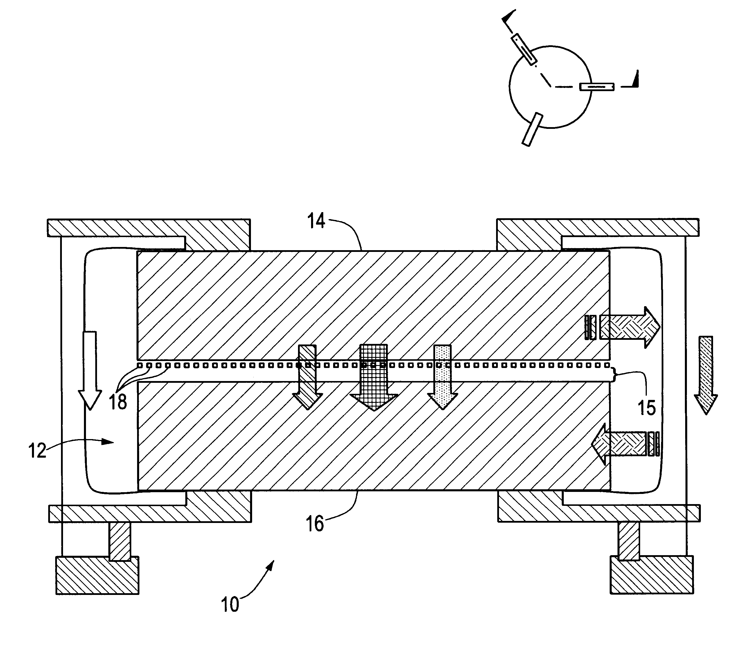
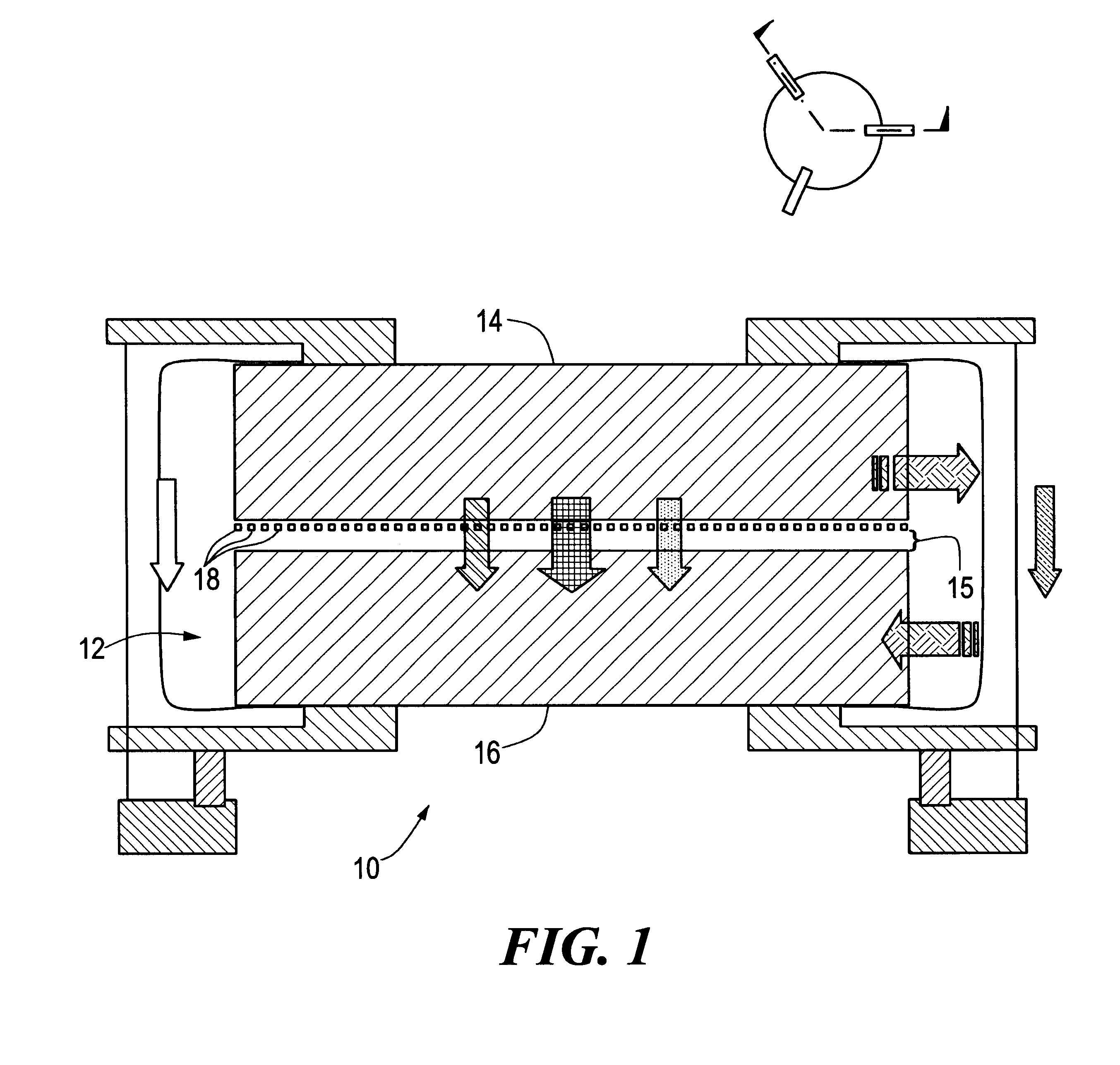
Microscale generator 10, FIG. 1, typically includes a pair of facing elements 14 and 16 within vacuum 12 having a temperature gradient therebetween. First element 14 acts as a thermal source for transferring energy and second element 16 receives the energy transferred. However, this is not a necessary limitation of the invention as element 16 could instead act as the thermal source while element 14 receives the energy. In order to maintain a fixed spacing between elements 14 and 16, one of the facing elements is sectioned into much smaller surface areas (referred to below as panels) which easily conform to variations in the surface of the facing element.

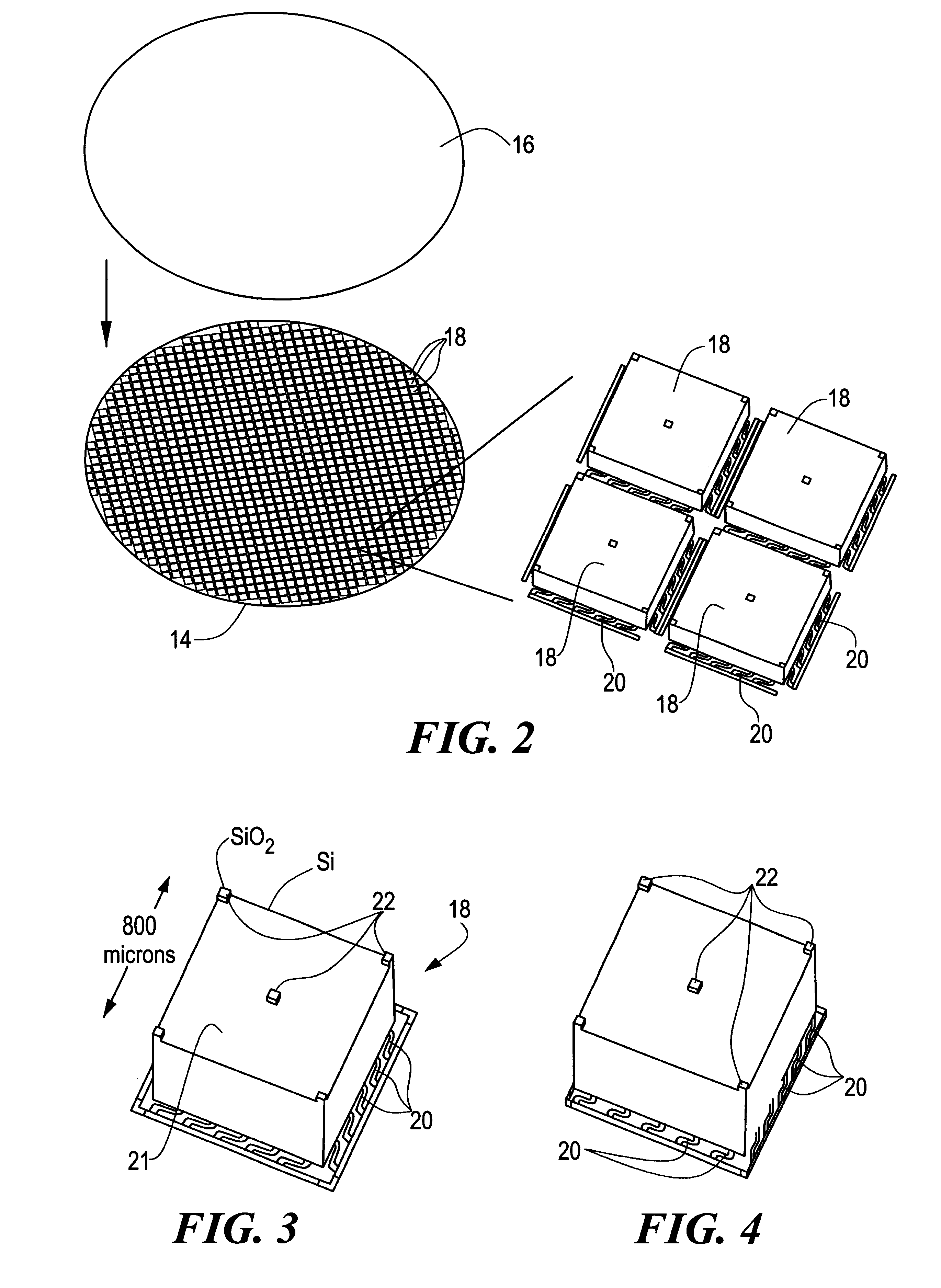
Disposed on one of the facing elements, shown here as first element 14, is an array of individual, independently passively or actively moveable panels 18 which are thermally coupled to element 14 and spaced from facing element 16 a predetermined, sub-micron distance to efficiently and evanescently couple the energy between elements 1...


PUM


Abstract

A microcavity apparatus and systems for maintaining microcavity spacing over a macroscopic area. An application of this invention is a microscale generator. This microscale generator includes a first element for receiving energy; a second element, opposite the first element for transferring energy; at least one panel on either of the first element or the second element, the panel facing the other element; a device for controlling the distance between the at least one panel and the facing element to form a predetermined, sub-micron gap between the panel and the facing element for increasing energy transfer to the element for receiving; and a device, responsive to the energy transfer, for generating electricity.

Description

This invention relates to a system for maintaining a microcavity over a microscale area. This invention also relates to thermophotovoltaic devices, and more particularly to a microscale thermophotovoltaic generator.BACKGROUND OF INVENTIONIt has been shown that electromagnetic energy transfer between a hot and a cold body is a function of the close spacing of the bodies due to evanescent coupling of near fields. Thus, the closer the bodies, approximately one micron and below, the greater the power transfer. For gap spacings of 0.1 microns, increases in power output of factors often are common.The dilemma, however, is maintaining the close spacing at a sub-micron gap in order to maintain the enhanced performance.While it is possible to obtain the sub-micron gap spacing, the thermal effects on the hot and cold surfaces induce cupping, warping or deformation of the elements resulting in variations in gap spacing thereby resulting in uncontrollable variances in the power output.Typically...

Claims


Application Information

Patent Timeline
IPC IPC(8): H01L31/04H01L31/18H01L37/00
CPCH02S10/30Y02E10/50H01L31/04H01L31/18
Inventor DIMATTEO, ROBERT STEPHENWEINBERG, MARC STEVENKIRKOS, GREGORY A.
Owner CHARLES STARK DRAPER LABORATORY
Why Eureka
Try Eureka