
Low swage load fastener and fastening system

Inactive Publication Date: 2001-05-22
HUCK INT INC
View PDF26 Cites 85 Cited by
  • Summary
  • Abstract
  • Description
  • Claims
  • Application Information

AI Technical Summary

Benefits of technology

The present invention relates to a fastening system including two-piece swage fasteners and more particularly to pull type swage fasteners with the present invention directed to a construction in which the tensile or relative axial loads required to swage the fastener are reduced permitting the use of smaller, lighter weight installation tools while providing a fastener having a preselected strength and a desirable weight and size.
It is another object of the present invention to provide a fastening system including a novel two-piece swage type fastener capable of being installed at substantially reduced relative axial loads and in which the pin has pull grooves of a generally helical contour and of a unique configuration to withstand the necessary installation loads.

Problems solved by technology

This causes less stress on the engaged threads of the mating threaded thimble or nut member on the pull tool resulting in longer life.
Such fastener also requires the application of a relatively high axial force for swaging and for final installation and accordingly requires a relatively large and heavy installation tool.

Method used


Image

  • Low swage load fastener and fastening system
  • Low swage load fastener and fastening system
  • Low swage load fastener and fastening system

Examples


Embodiment Construction

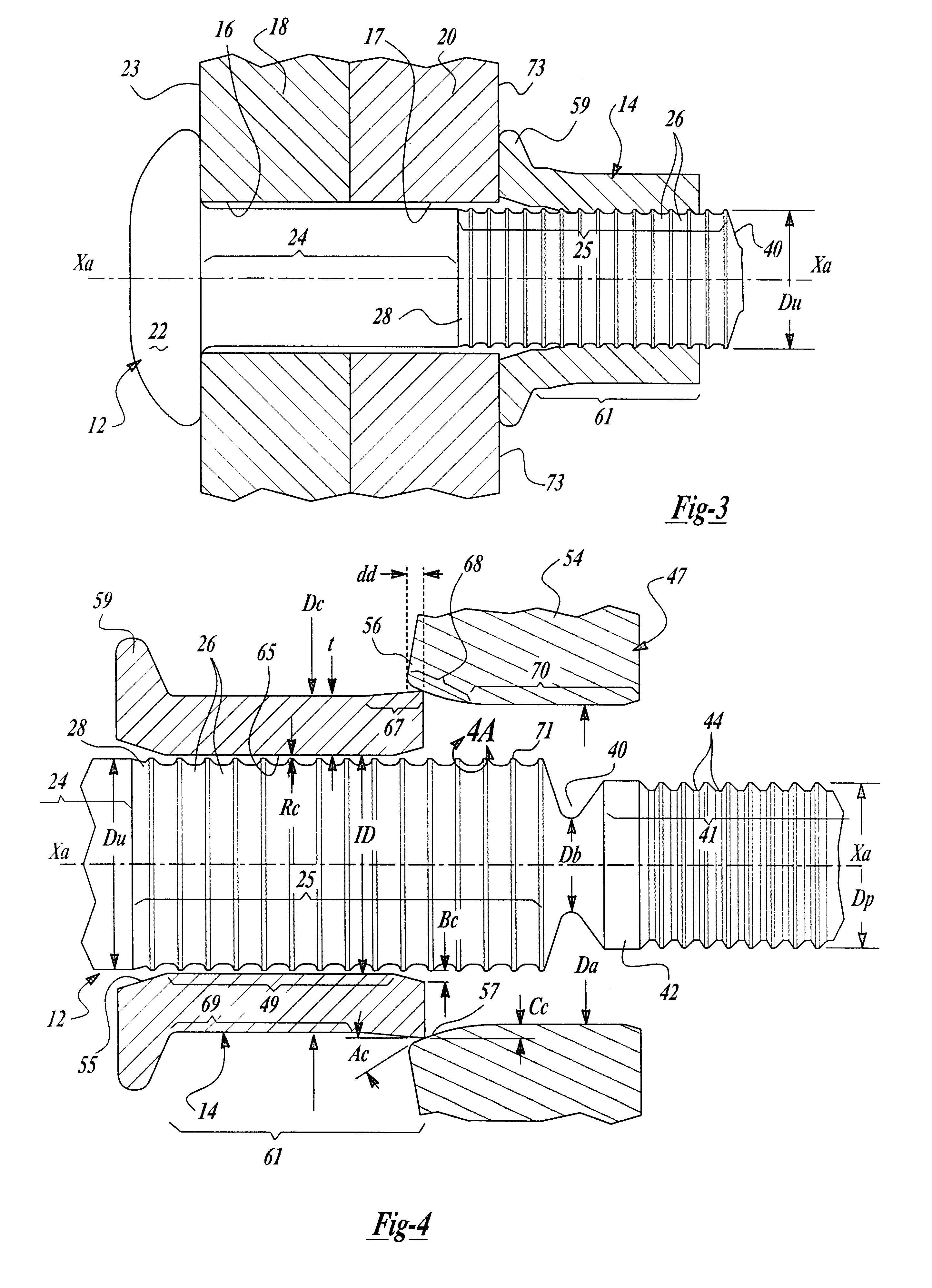
In the discussion which follows references are made to various components and a list of typical, average values for such components over a range of different sized fasteners of one form of the present invention and conventional fasteners of the same grade is provided in a CHART OF TYPICAL VALUES.

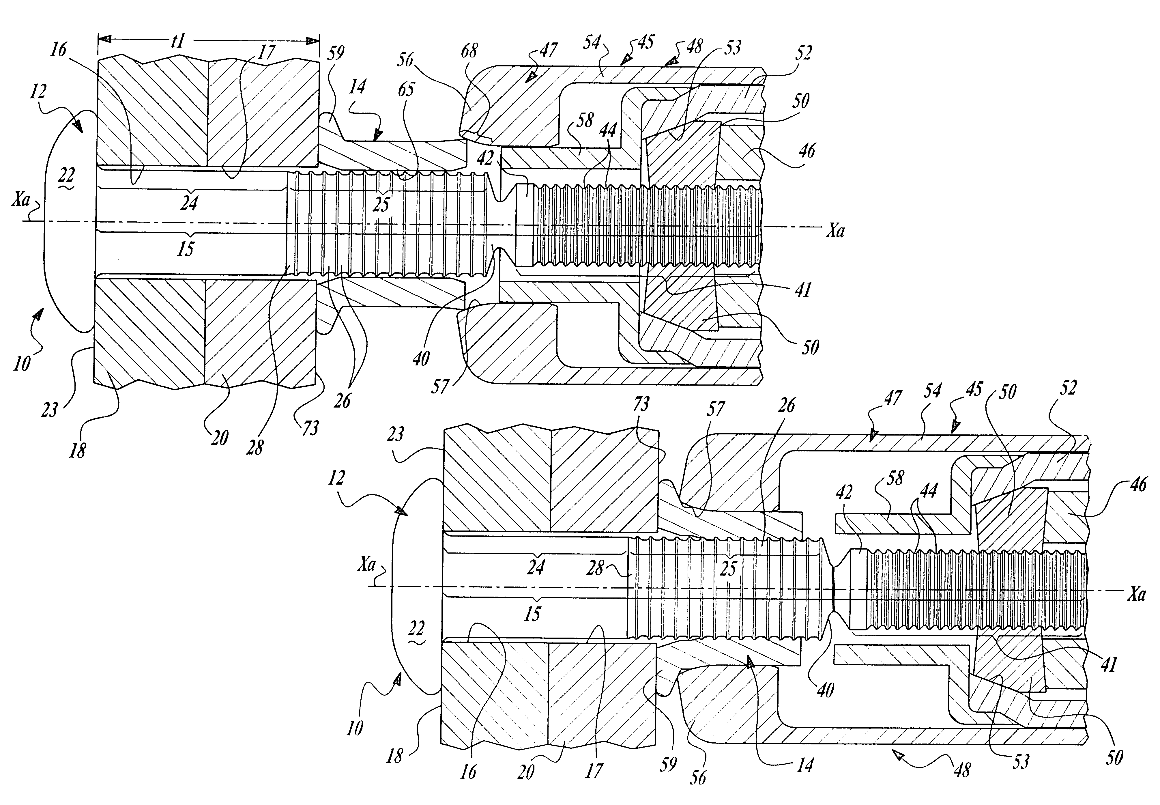
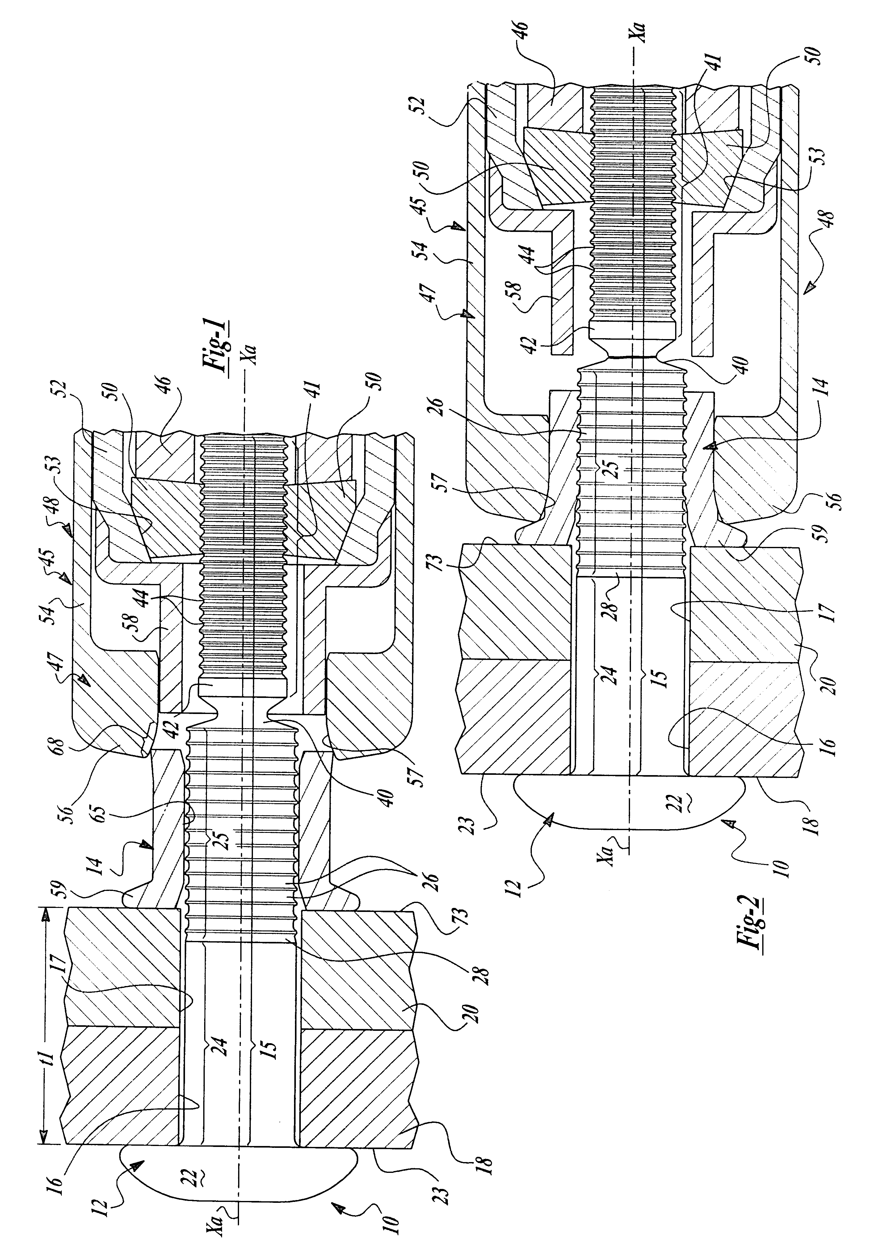
Looking now to FIGS. 1-4, a fastener 10 is shown and includes a pin member 12 and tubular collar 14. Pin member 12 has an elongated shank 15 which extends through aligned openings or bores 16 and 17 in a pair of workpieces 18 and 20, respectively, to be secured together. An enlarged protruding head 22 at one end of shank 15 engages the back side surface 23 of workpiece 18. The shank 15 has a straight, smooth cylindrical shank portion 24 adjacent the head 22 which is adapted to be received within the aligned bores 16 and 17 with a clearance fit. It should be understood, however, that in some installations the straight shank portion 24 can be sized to provide a close tolerance or desired inter...


PUM

PropertyMeasurementUnit
Fractionaaaaaaaaaa
Fractionaaaaaaaaaa
Fractionaaaaaaaaaa

Abstract

A fastening system including a two piece swage type fastener including a pin and a collar in which the pin has relatively wide lock grooves and in which the lock grooves have a generally smooth root contour with the collar having a shank portion with a wall thickness defining an excess volume of material prior to swage greater than the volume of the confronting lock grooves and with the clearance between the inside diameter of the collar shank portion and the diameter of crests of the lock grooves being a minimum to reduce the compressive force required to swage the collar shank into the lock grooves and with the excess volume of collar shank material providing only a partial fill of the lock grooves upon swage.

Description

SUMMARY BACKGROUND OF THE INVENTIONThe present invention relates to a fastening system including two-piece swage fasteners and more particularly to pull type swage fasteners with the present invention directed to a construction in which the tensile or relative axial loads required to swage the fastener are reduced permitting the use of smaller, lighter weight installation tools while providing a fastener having a preselected strength and a desirable weight and size.The present invention relates to two-piece swage type fasteners or lockbolts generally of the type illustrated in U.S. Pat. No. 2,531,048 to L. Huck, issued Nov. 21, 1950, and U.S. Pat. No. 3,215,024 to Brilmyer et al issued Nov. 2, 1965; there are numerous other variations of swage type fasteners such as U.S. Pat. No. 3,915,053 to J. Ruhl, issued Oct. 28, 1975, U.S. Pat. No. 4,472,096 to J. Ruhl and R. Dixon, issued on Sep. 18, 1984 and U.S. Pat. No. 5,090,852 to R. Dixon, issued Feb. 25, 1992.In many commercial applicat...

Claims


Application Information

Patent Timeline
IPC IPC(8): B21J15/00B21J15/02F16B19/04F16B19/05F16B19/08
CPCB21J15/022B21J15/28B21J15/285F16B19/05Y10T29/53065Y10T29/53735Y10T29/53726F16B19/08
Inventor FULBRIGHT, DAVID J.
Owner HUCK INT INC
Learn More