
Micro vacuum pump for maintaining high degree of vacuum and apparatus including the same

a vacuum pump and vacuum technology, applied in vacuum obtaining/maintenance, tubes with screens, instruments, etc., can solve the problems of deterioration of the capability of exhausting rare gases, i.e. inert gases, and the inability to ensure the quality and performance of vacuum pumps

Inactive Publication Date: 2001-05-22
NEC CORP
View PDF10 Cites 24 Cited by
  • Summary
  • Abstract
  • Description
  • Claims
  • Application Information

AI Technical Summary

Problems solved by technology

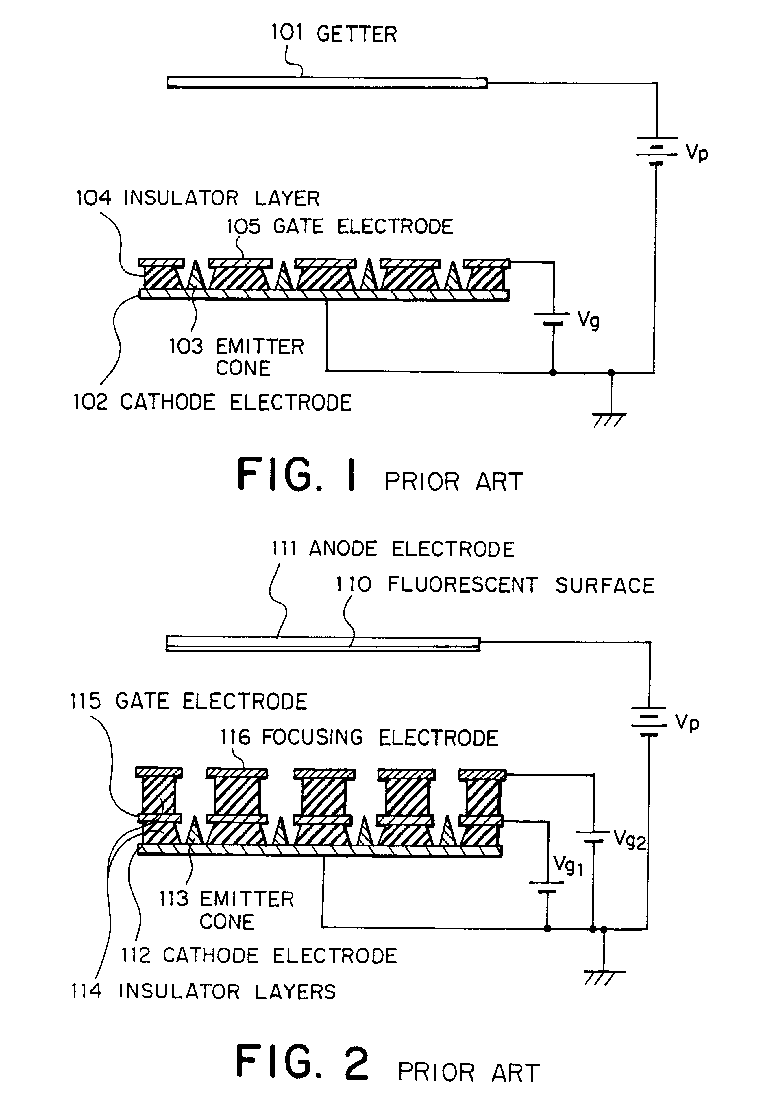
Hence, active gases including oxygen- and carbon-based gases can be adsorbed, however, inert gases including argon cannot be adsorbed.
Thus, there has been a problem in that the capability of exhausting rare gases, i.e. inert gases, is deteriorated and the quality and performance required of the vacuum pumps cannot be ensured.
This means that unstable images, deteriorated luminance, or shorter service life has been observed when driving a CRT, flat panel display, or the like in such a vacuum environment.
Further, in the vicinity of the emitter cones or the protrusions, ionized residual gases such as argon having a high sputtering yield pour down on the negative-electrode protrusions and inevitably damage the protrusions that emit electrons in the getter device.
This leads to marked deterioration in the electron emitting property and makes it difficult to retain stable gettering performance with good repeatability over a long period of time.

Method used


Image

  • Micro vacuum pump for maintaining high degree of vacuum and apparatus including the same
  • Micro vacuum pump for maintaining high degree of vacuum and apparatus including the same
  • Micro vacuum pump for maintaining high degree of vacuum and apparatus including the same

Examples


Embodiment Construction

The embodiments of the invention will be described with reference to the accompanying drawings.

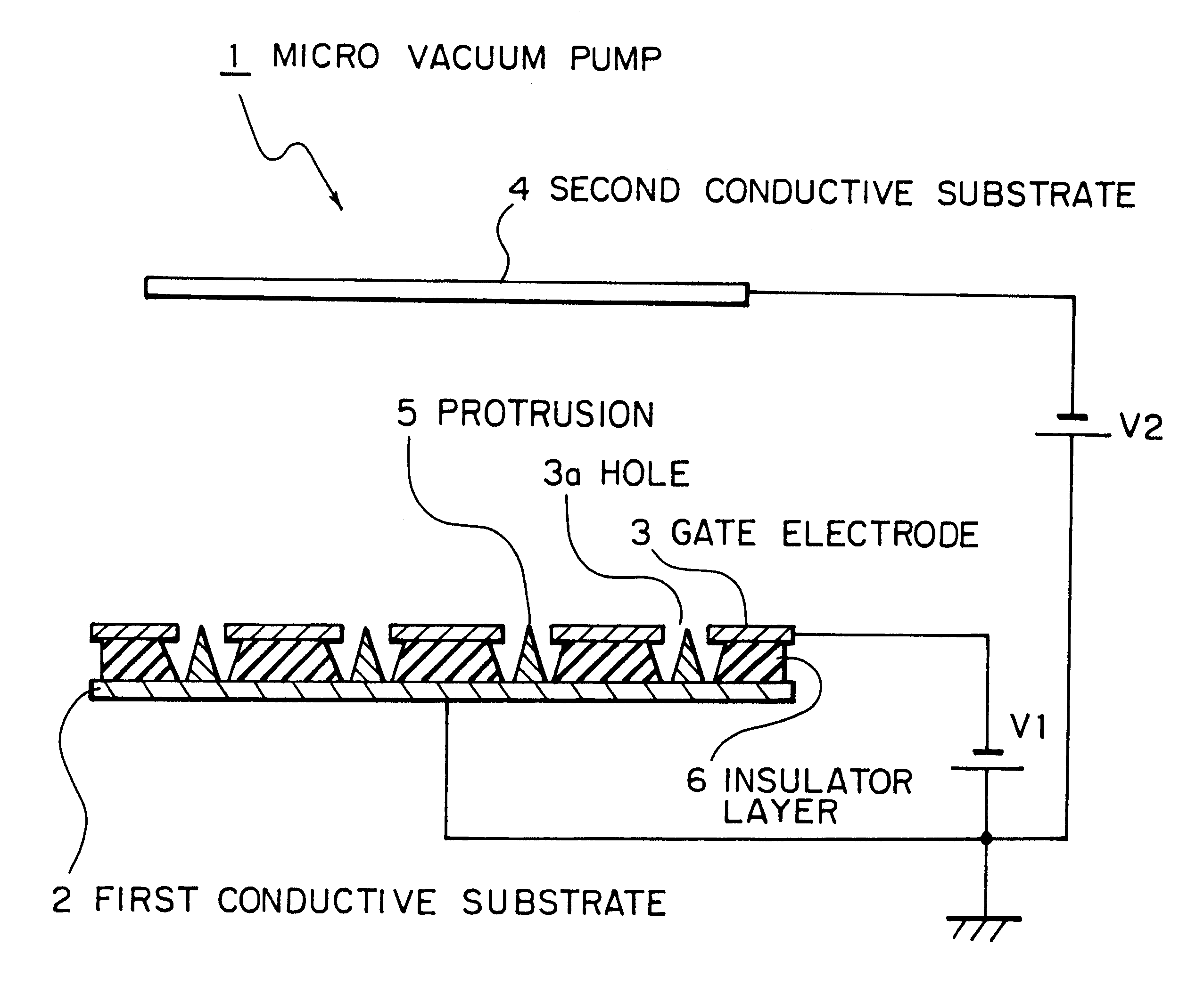
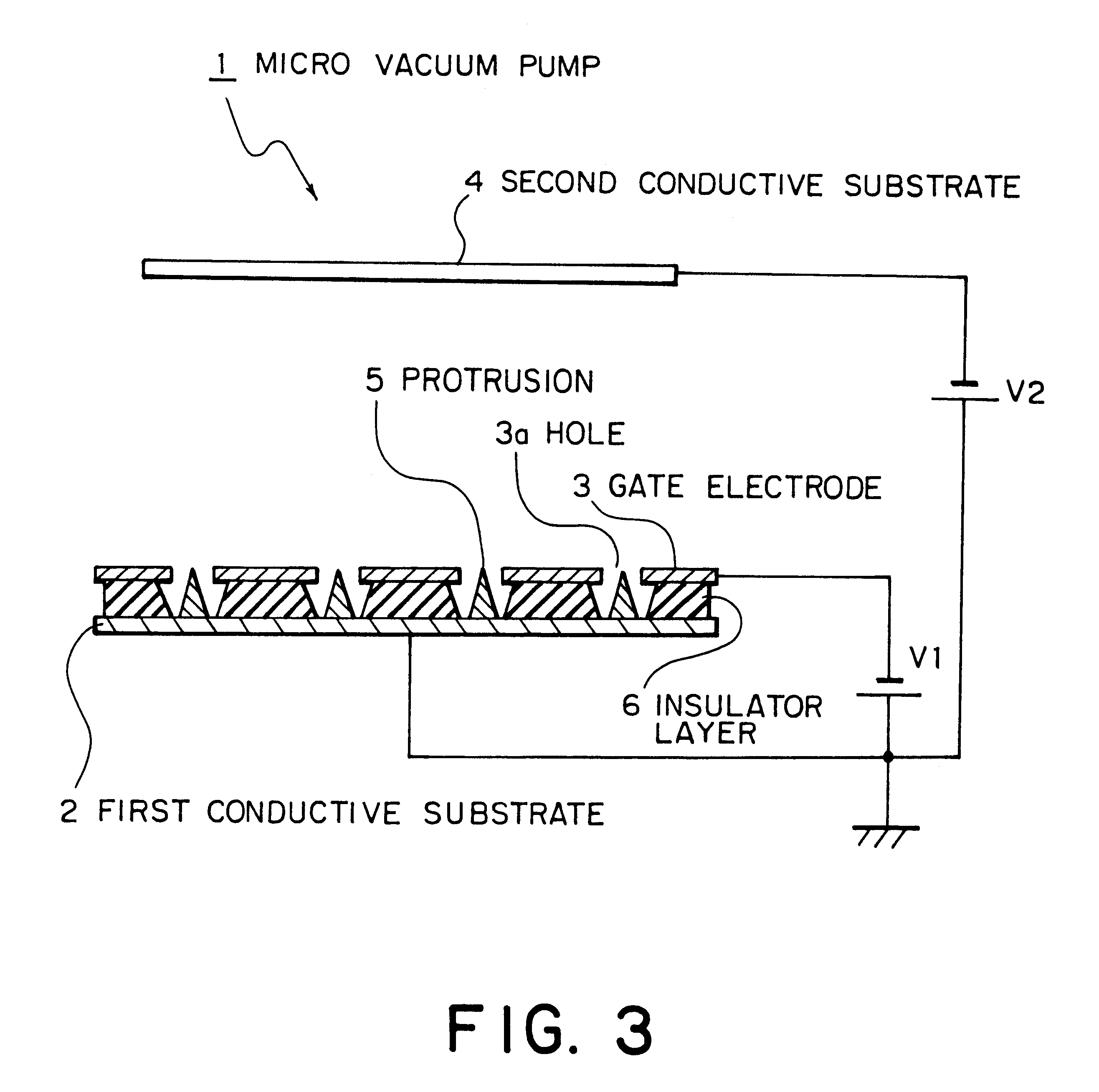
FIG. 3 is a sectional schematic representation illustrating a first embodiment in accordance with the present invention. A micro vacuum pump 1 shown in FIG. 3 includes a first conductive substrate 2, a gate electrode 3, and a second conductive substrate 4 as chief constituents, and the micro vacuum pump is disposed in a vacuum chamber.

The present invention is characterized by the following.

The first conductive substrate 2 is a heavily doped N silicon substrate. Provided on the surface of the first conductive substrate 2 facing the second conductive substrate 4 are many (e.g. 10.sup.6 pieces) micro protrusions 5 composed of a metal having a high melting point such as molybdenum or a semiconductor element such as silicon. The first conductive substrate 2 has the gate electrode 3 mounted via an insulator layer 6 on the surface thereof opposed to the second conductive substrate 4.

The gate elec...


PUM


Abstract

The present invention provides a micro vacuum pump capable of enhancing the performance of exhausting rare gases as well as active gases thereby to ensure quality, good repeatability and stable getter action of the micro vacuum pump over a long time. The invention also provides an apparatus assembling the micro vacuum pump. The micro vacuum pump capable of maintaining a high degree of vacuum includes a first conductive substrate having many protrusions and mounting a second conductive substrate disposed with a predetermined interval provided with respect to the first conductive substrate so that it faces the protrusions. A gate electrode is disposed in the vicinity of the apexes of the protrusions on the first conductive substrate via an insulator layer, and is positioned to face the second conductive substrate. Relative to the first conductive substrate, a negative potential is supplied to the second conductive substrate, and, a same negative potential difference is also applied to the gate electrode relative to the cones.

Description

1. Field of the InventionThe present invention relates to a micro vacuum pump for maintaining vacuum in a chamber and an apparatus including the same. And, more particularly, the present invention relates to a micro vacuum pump that is capable of maintaining a high degree of vacuum, enhancing exhaust performance, and securing quality over an extended period of time.2. Description of Related ArtMost apparatuses requiring a vacuum environment employ diverse exhausting methods to enhance the degree of internal vacuum. For example, there are semiconductor manufacturing apparatuses incorporating deposition treatment units, dry etching units, etc., or surface observing apparatuses incorporating electron microscopes, etc. These apparatuses employ ion pumps or turbo-molecular pumps or other types of vacuum pumps that are large and provide high exhausting speed to exhaust the interior of the vacuum chambers of the apparatuses at all times thereby to maintain a high degree of vacuum.Vacuum ai...

Claims


Application Information

Patent Timeline
IPC IPC(8): H01J41/00H01J41/06H01J29/94H01J29/04H01J31/12H01J41/12
CPCH01J41/06H01J9/385H01J29/94H01J41/18H01J2329/945
Inventor ITO, FUMINORI
Owner NEC CORP
Learn More