Dielectric filter having at least one stepped resonator hole with a recessed or protruding portion, the stepped resonator hole extending from a mounting surface

Inactive Publication Date: 2001-05-22
MURATA MFG CO LTD
View PDF16 Cites 14 Cited by
  • Summary
  • Abstract
  • Description
  • Claims
  • Application Information

AI Technical Summary

Benefits of technology

Accordingly, it is an object of the present invention to provide a dielectric filter and a dielectric duplexer which can be easily made compact and which can be conne

Problems solved by technology

Since the distance between the axes of adjacent resonator holes, which specifies the degree of coupling in the dielectric filter, is set to a certain length, however, the diameter of the large-diameter hole sections is limited.
On the other hand, it is difficult to extremely

Method used


Image

  • Dielectric filter having at least one stepped resonator hole with a recessed or protruding portion, the stepped resonator hole extending from a mounting surface
  • Dielectric filter having at least one stepped resonator hole with a recessed or protruding portion, the stepped resonator hole extending from a mounting surface
  • Dielectric filter having at least one stepped resonator hole with a recessed or protruding portion, the stepped resonator hole extending from a mounting surface

Examples


Example

[First Embodiment, FIG. 1 to FIG. 8]

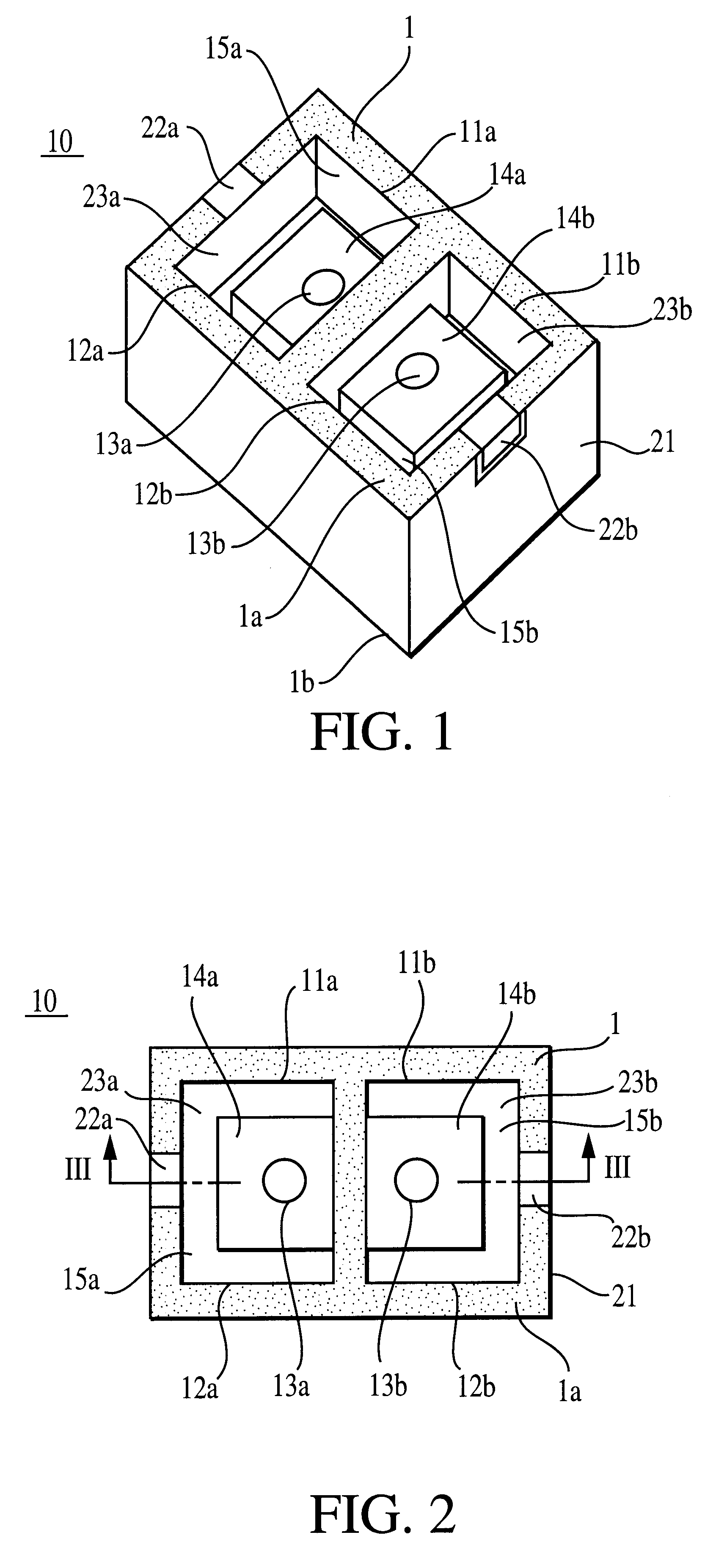
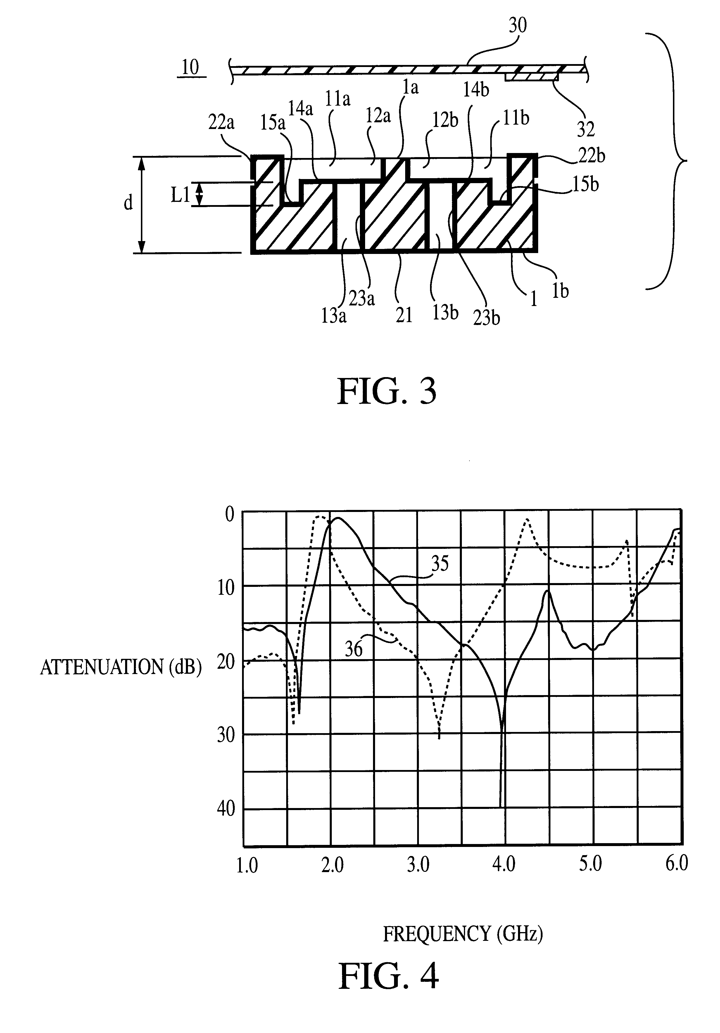
As shown in FIG. 1 to FIG. 3, a dielectric filter 10 has two resonator holes 11a and 11b passing through opposing surfaces 1a and 1b of a dielectric block 1. The resonator holes 11a and 11b have large and rectangular cross-sectional hole portions 12a and 12b as large-sectional area portions, and small and circular cross-sectional hole portions 13a and 13b as small-sectional area portions mechanically connected to the large-sectional area portions 12a and 12b, respectively. The axes of the large-sectional area portions 12a and 12b shift from those of the small-sectional area portions 13a and 13b. The degree of coupling in the dielectric filter 10 is determined by the distance of the axes of the adjacent large-sectional area portions 12a and 12b, the distance between the axes of the small-sectional area portions 13a and 13b, and other factors.

On step portions 14a and 14b at the boundaries of the large-sectional area portions 12a and 12b and the smal...

Example

[Second Embodiment, FIG. 8]

As shown in FIG. 8, a dielectric filter 18 according to a second embodiment has the same configuration as the dielectric filter 10 according to the first embodiment, except for an outer conductor 21, inner conductors 23a and 23b, and input and output electrodes 22a and 22b. The outer conductor 21 is formed almost all outer surfaces of a dielectric block 1. The pair of input and output electrodes 22a and 22b are formed on outer surfaces of the dielectric block 1 without electrically connecting to the outer conductor 21 with a gap from the outer conductor 21. The input and output electrodes 22a and 22b are connected to an external circuit through a capacitor or other elements as required.

The inner conductors 23a and 23b are formed on almost all inner surfaces of resonator holes 11a and 11b. Gaps 19 are provided between the inner conductors 23a and 23b and the outer conductor 21 extending to the opening sections of large-sectional area portions 12a and 12b. T...

Example

[Third Embodiment, FIG. 9 and FIG. 10]

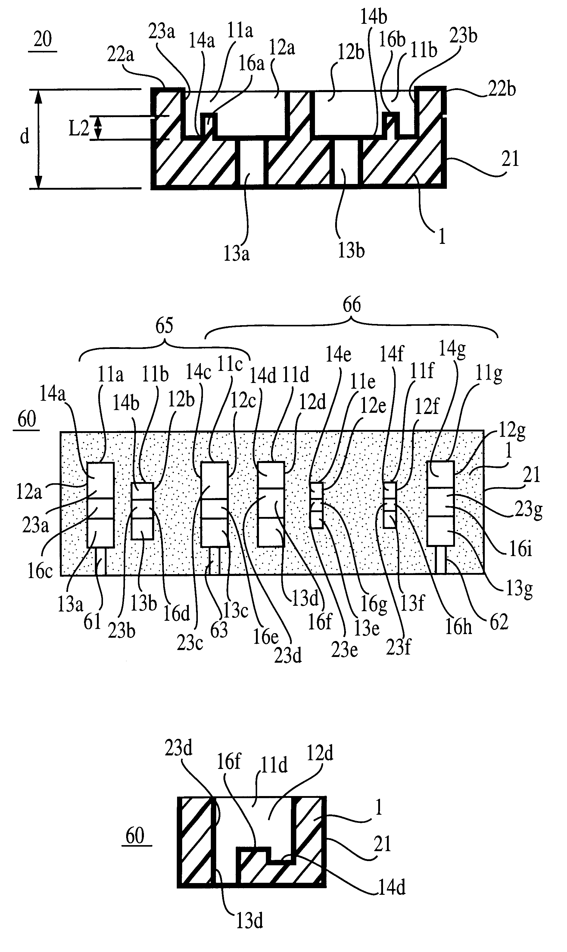
As shown in FIG. 9 and FIG. 10, in a dielectric filter 20, protruding portions 16a and 16b are formed on step portions 14a and 14b in resonator holes 11a and 11b with a certain distance from small-sectional area portions 13a and 13b. The protruding portions 16a and 16b are formed such that they surround about three-fourths the small-sectional area portions 13a and 13b with the adjacent inner surfaces of large-sectional area portions 12a and 12b being left.

In the dielectric filter 20 configured as described above, since the protruding portions 16a and 16b are formed on the step portions 14a and 14b, the conductive-path lengths of the inner conductors 23a and 23b become longer than those in a conventional dielectric filter having no protruding portions by twice the length L2 of the side walls of the protruding portions 16a and 16b. Therefore, with the same center frequency, the dielectric filter 20 can have a shorter axial length "d" of the resona...


PUM


Abstract

A dielectric filter (10, 20) is provided with resonator holes 11a and 11b, and the resonator holes 11a and 11b have large-sectional area portions 12a and 12b and small-sectional area portions 13a and 13b, respectively. On the step portions 14a and 14b between the large-sectional area portions 12a and 12b and the small-sectional area portions 13a and 13b, grooves 15a and 15b or protruding portions 16a and 16b substantially surround the small-sectional area portions 13a and 13b, respectively. Inner conductors 23a and 23b formed on the inner surfaces of the resonator holes 11a and 11b are directly connected to input and output electrodes 22a and 22b formed on outer surfaces of a dielectric block 1.

Description

1. Technical Field of the InventionThe present invention relates to a dielectric filter, a dielectric duplexer, and a communication apparatus using the same.2. Related Art of the InventionThere has been known a dielectric filter used for a mobile communication unit, which has a single dielectric block in which a plurality of resonator holes are provided. The resonator holes have large-diameter hole sections and small-diameter hole sections mechanically connected to each other, and also have step portions between the large-diameter hole sections and the small-diameter hole sections. Inner conductors are formed on the inner surfaces of the resonator holes, and an outer conductor is formed on almost all outer surfaces of the block except for one opening end face among both end faces where the resonator holes have openings. The inner conductors are electrically disconnected (open) at one opening end face (open-circuited end face) and electrically short-circuited (connected) at the other...

Claims


Application Information

Patent Timeline
IPC IPC(8): H01P1/213H01P1/20H01P1/205H01P1/212
CPCH01P1/2056H01P1/2136H01P1/2084H01P1/2138
Inventor TSUJIGUCHI, TATSUYA
Owner MURATA MFG CO LTD
Why Eureka
Try Eureka