

Heat pump type refrigerant cycle system
a refrigerant cycle and heat pump technology, applied in refrigeration components, transportation and packaging, light and heating equipment, etc., can solve the problems of increasing the number of components of the refrigerant cycle system, increasing the complexity of the refrigerant pipe structure, and insufficient heat capacity of the passenger compartmen
- Summary
- Abstract
- Description
- Claims
- Application Information
AI Technical Summary
Benefits of technology
Problems solved by technology
Method used
Image

Examples
first embodiment
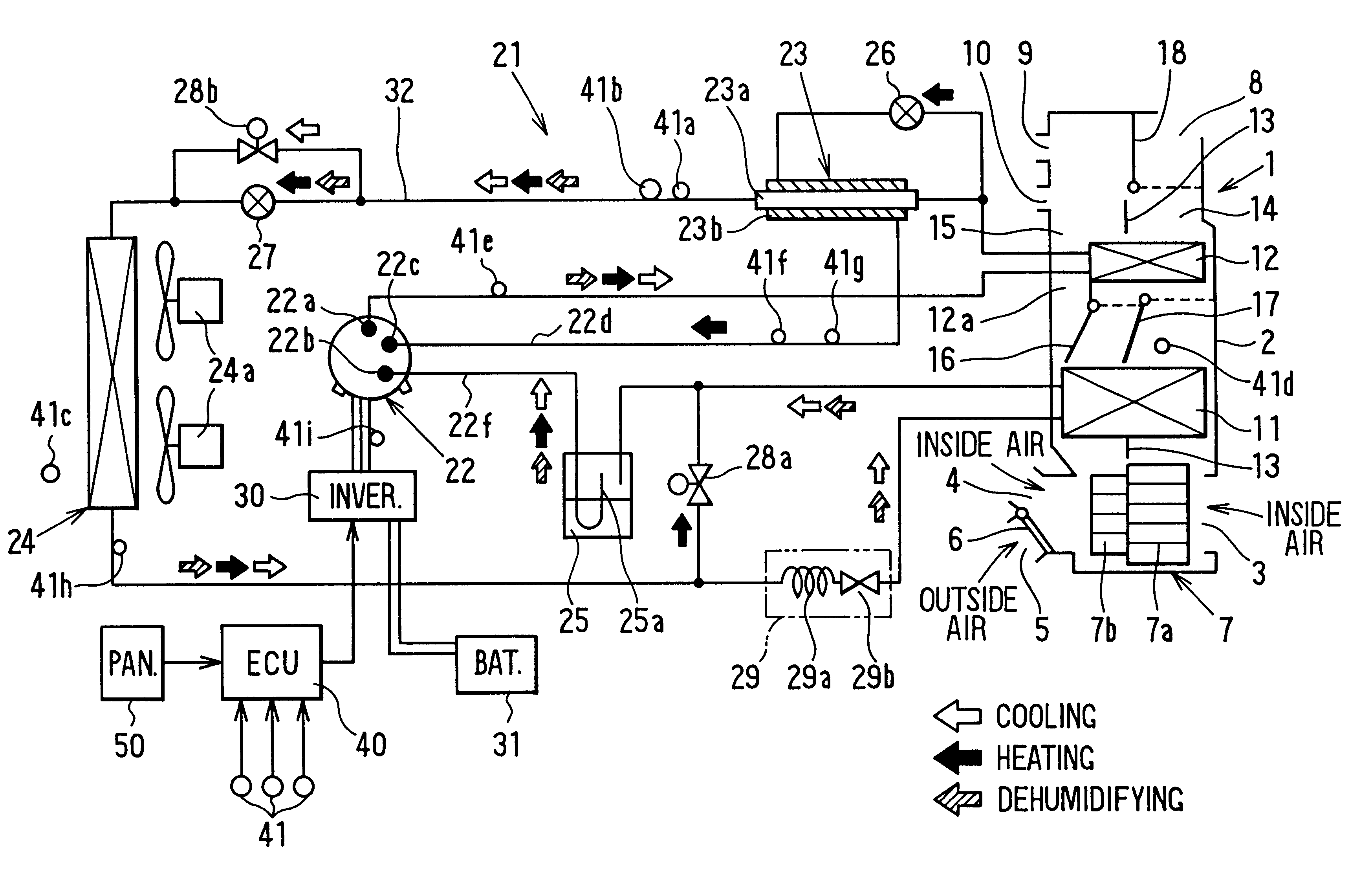
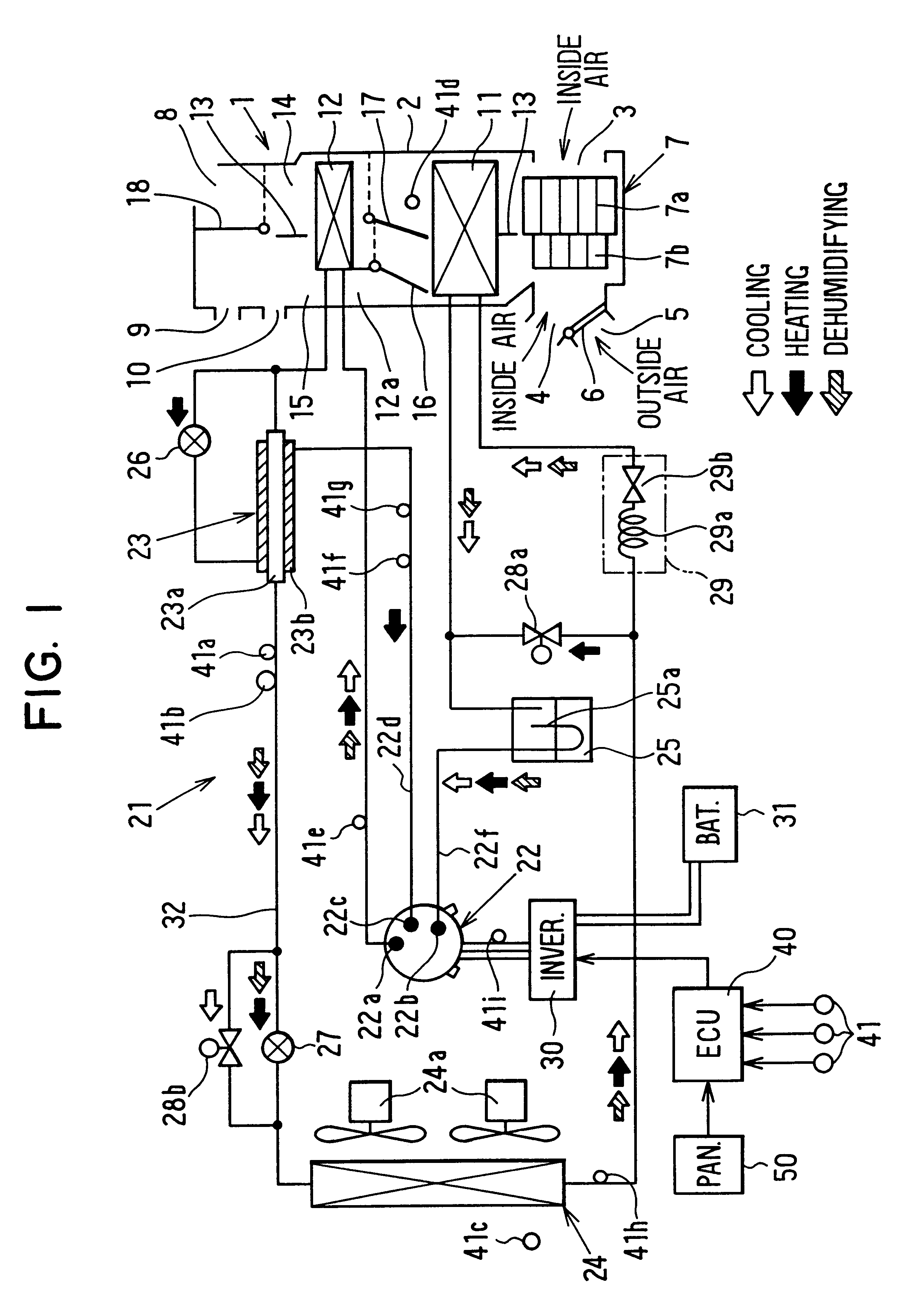
A first preferred embodiment of the present invention will be now described with reference FIGS. 1-11. In a refrigerant cycle system of the first embodiment, the present invention is typically applied to an air conditioner for an electric vehicle. As shown in FIG. 1, an air conditioning unit 1 is disposed within a passenger compartment, and an air conditioning duct 2 of the air conditioning unit 1 forms an air passage for introducing conditioned air into the passenger compartment. Air inlets 3, 4, 5 are formed at an end of the air conditioning duct 2 for sucking inside / outside air. The air inlet 4 for sucking inside air (i.e., air inside the passenger compartment) and the air inlet 5 for sucking outside air (i.e., air outside the passenger compartment) are switched to be open or closed by an inside / outside air switching door 6.
A blower 7 for blowing air into the air conditioning duct 2 is disposed adjacent to the air inlets 3-5. The blower 7 includes a motor and centrifugal fans 7a,...
fourth embodiment
In the present invention, as shown in FIG. 15, the bypass passage 60 is branched from a bypass passage 61 where the first pressure reducing unit 26 is provided. However, the bypass passage 60 may be branched from a main passage 62 connecting the outlet of the condenser 12 and the inlet of the refrigerant-refrigerant heat exchanger 23.
In the fourth embodiment of the present invention, the operation of the refrigerant cycle system during the heating mode or the dehumidifying mode is similar to that in the above-described first embodiment, and the explanation thereof is omitted.
A fifth preferred embodiment of the present invention will be now described with reference to FIGS. 16, 17. FIG. 16 shows a refrigerant cycle system according to the fifth embodiment. As shown in FIG. 16, in the fifth embodiment, liquid refrigerant staying in the gas injection passage 22d is introduced into an upstream refrigerant side of the accumulator 25 during the heating mode, so that liquid refrigerant is ...
fifth embodiment
In the fifth embodiment, a valve port diameter (i.e., valve opening area) of the electromagnetic valve 28d is set to be larger than a port diameter of the gas injection port 22c of the compressor 22, so that refrigerant in the gas injection passage 22d flows into the accumulator 25 through the bypass passage 63 when the electromagnetic valve 28d is opened. However, when it is difficult to set the valve port diameter of the electromagnetic valve 28d to be larger than the port diameter of the gas injection port 22c of the compressor 22, an additional electromagnetic valve is further disposed between a branch port 63a of the bypass passage 63 and the gas injection port 22c of the compressor 22, and the additional electromagnetic valve is closed when the electromagnetic valve 28d is opened.
Next, operation of the refrigerant cycle system according to the fifth embodiment of the present invention will be now described with reference to FIG. 17. The control routine shown in FIG. 17 is star...
PUM
 Abstract
Description
Claims
Application Information