Image formation apparatus and image formation method

a technology of image formation apparatus and image, which is applied in the direction of recording apparatus, visual presentation using printers, instruments, etc., can solve the problems of large number of parts, large device itself, and large cost increase of devices

Inactive Publication Date: 2001-05-29
SHARP KK
View PDF27 Cites 20 Cited by
  • Summary
  • Abstract
  • Description
  • Claims
  • Application Information

AI Technical Summary

Problems solved by technology

However, in the configuration of the four drum type image formation apparatus disclosed in Japanese Unexamined Patent Publication JP-A 58-95361(1983), since four light sensitive elements are provided each with a charger, a developing device and a transfer unit, the number of parts is large.
Thus, the device is enlarged so that a problem of cost increase of the device is generated.
As a consequence, a problem occurs in that the device itself needs to be large.
Accordingly, there is a problem in that a long time is required for obtaining a full color image.
Thus, downsizing or cost reduction of a fu

Method used


Image

  • Image formation apparatus and image formation method
  • Image formation apparatus and image formation method
  • Image formation apparatus and image formation method

Examples


example 2

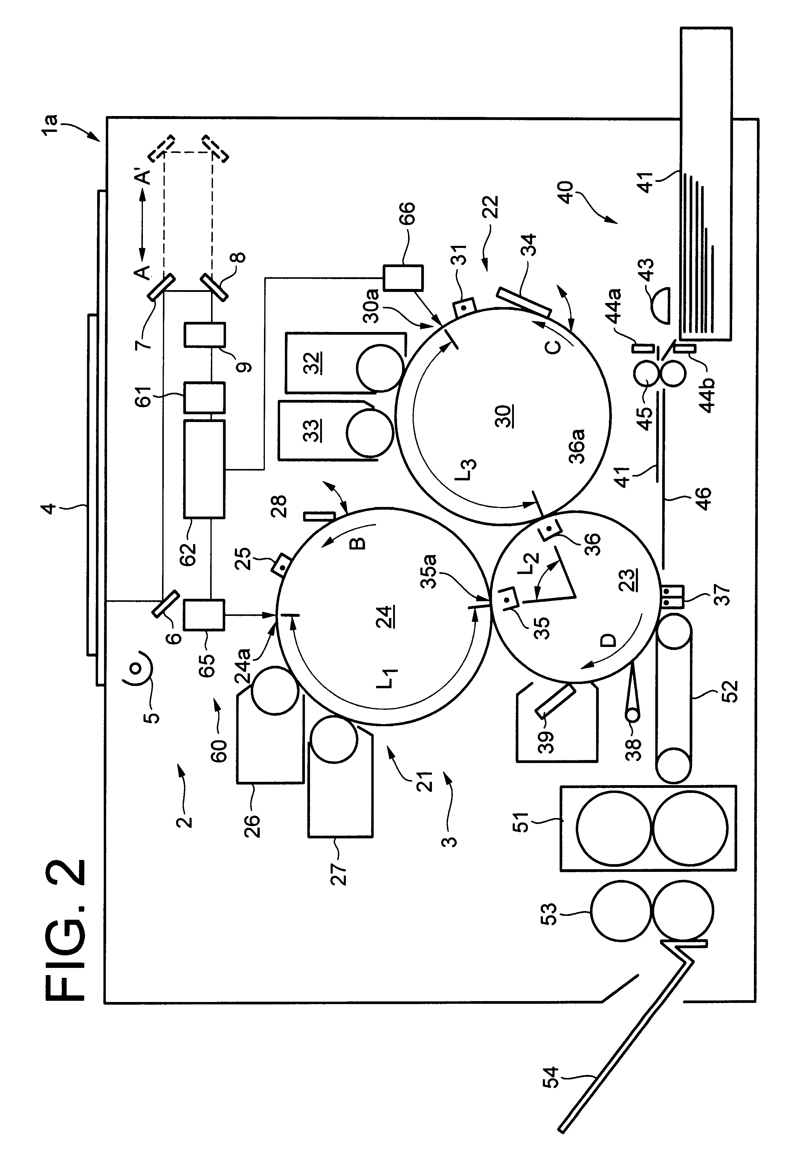
of the present invention will be explained with reference to FIGS. 2 and 3. The members having the same function as in Example 1 have the same numerals and further explanation will not be provided herein.

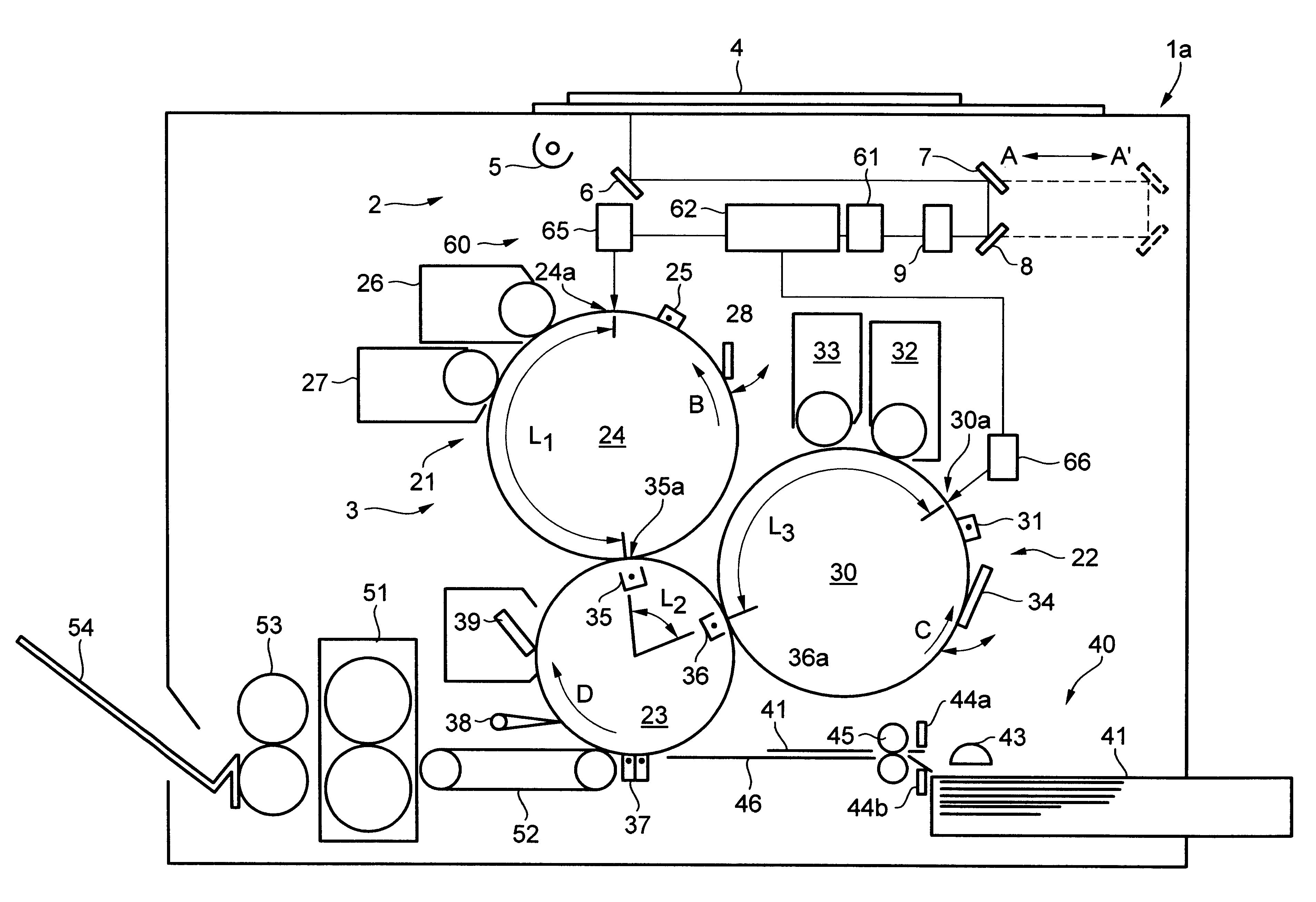
In an image formation apparatus 1a of Example 2, as shown in FIG. 2, an image portion 60 is provided in place of the half mirror 10, filters 14 to 17 at the light flux output side of the zoom lens 9.

As shown in FIG. 3, the image process portion 60 comprises an image pick-up portion 61, an image signal processing portion 62 (image signal generation means), a page memory 63 (first memory means), a multiplexed 64 (image signal selection means), light sensitive element exposure devices 65, 66 (first light sensitive element exposure means, second light sensitive element exposure means), and CPU (central processing unit) 67.

The image pick-up portion 61 comprises a CCD (charge coupled device) as a color photoelectric transfer element so that an original image is formed on the CCD. The CCD ...

example 3

of the present invention will be explained with reference to FIGS. 2 and 5. The members having the same function as in Example 2 have the same numerals and further explanation will not be provided herein.

As shown in FIG. 5, the image process portion 70 of Example 3 has a configuration without the page memory 63 in the image process portion of FIG. 4. (see FIG. 3). At the time of the first original exposure, the image signals corresponding to yellow (Y) are selectively sent out to the light sensitive element exposure device 65 by the multiplexed 64 as well as the image signals corresponding to magenta (M) are selectively sent out to the light sensitive element exposure device 66. At the time of the second original exposure the image signals corresponding to cyan (C) are selectively sent out to the light sensitive element exposure device 65 as well as the image signals corresponding to black (BK) are selectively sent out to the light sensitive element exposure device 66. The configura...

example 4

of the present invention will be explained with reference to FIGS. 2 and 6. The members having the same function as in Examples 2 and 3 have the same numerals and further explanation will not be provided herein.

Although the first exposure portion 24a, the second exposure portion 30a, the first transfer portion 35a, and the second transfer portion 36a are arranged so as to satisfy L.sub.1 +L.sub.2 =L.sub.3. In this embodiment, the constituents are arranged so as to satisfy L.sub.1 +L.sub.2

As shown in FIG. 6, the image process portion 80 of Example 4 comprises a small capacity memory 68 (second memory means) having a smaller memory capacity with respect to the page memory 63 used in Example 2 (see FIG. 2). The image signals corresponding to magenta (M) and black (BK) outputted from the image signal processing portion 62 are directly sent to the light sensitive element exposure device 6...


PUM


Abstract

Developing devices are provided adjacent to a light sensitive element. An intermediate transfer drum is provided adjacent to the light sensitive elements. After exposure of the light sensitive element, a first color or third color image is formed on the light sensitive element. On the other hand, after exposure of the light sensitive element, a second color or fourth color image can be formed on the light sensitive element. The first color image is transferred from the transfer unit to the intermediate transfer drum at the first transfer portion, and the second color image is transferred from the transfer unit at the second transfer portion so as to be superimposed on the first color image. Similarly, the third color image is transferred so as to be superimposed on the second image and the fourth color image is transferred so as to be superimposed on the third color image to the intermediate transfer drum. Accordingly, the first to fourth color images are superimposed. Thereby, downsizing of the device and cost reduction are achieved and image formation speed is facilitated.

Description

1. Field of the InventionThe invention relates to a multicolor or full color image formation apparatus, such as a printer, a copying machine, and a facsimile, and an image formation method.2. Description of the Prior ArtsA conventional four drum type configuration, which comprises four light sensitive elements provided with one each developing device, used in a full color image formation apparatus utilizing an electrophotography method is disclosed in Japanese Unexamined Patent Publication JP-A 58-95361(1983).The image formation apparatus disclosed in the official gazette comprises a first process portion for forming an image with a first color 101, a second process portion for forming an image with a second color 102, a third process portion for forming an image with a third color 103, and a fourth process portion for forming an image with a fourth color 104 as illustrated in FIG. 10.The first process portion 101 comprises a light sensitive element 105, a charger 106 for charging t...

Claims


Application Information

Patent Timeline
IPC IPC(8): G03G15/01G06K15/12G03G15/00G03G15/16H04N1/23
CPCG06K15/129G03G15/0184G03G2215/0106
Inventor SHIMAZAWA, YOICHIMATSUDA, HIDEOMAEDA, YASUTAKAANZAI, SHUNJUFUJIMOTO, OSAMUSAKAGAMI, HIDEKAZUIRIE, KAZUMI
Owner SHARP KK
Why Eureka
Try Eureka