Die apparatus for cutting end of bumper bar

a technology of bumper bars and dies, which is applied in the direction of tube shearing machines, metal working apparatuses, manufacturing tools, etc., can solve the problems of inability to adapt the rollforming apparatus and methods, inability to use ultra-high strength materials, and inability to easily deform or cut tubular bumpers. achieve the effect of high strength

Inactive Publication Date: 2001-06-05
SHAPE CORP
View PDF38 Cites 40 Cited by
  • Summary
  • Abstract
  • Description
  • Claims
  • Application Information

AI Technical Summary

Benefits of technology

In one aspect of the present invention, a die apparatus is provided that is adapted to engage and cut an end of a tubular bar made from high strength sheet steel, the tubular bar having walls forming first and second tubular sections that define first and second cavities with the walls further defining a third cavity between the first and second cavities. The die apparatus includes a first die configured to telescopingly engage an end section of the tubular bar, including first...

Problems solved by technology

The rollforming apparatuses and methods disclosed in the above-noted patents are adapted to manufacture a continuous tubular bumper section, which continuous tubular bumper section may have pre-pierced or pre-punched holes, but the rollforming apparatuses and methods are not adapted to make a tubular bumper section having a compound angle on ends of the bumper sections.
This presents a problem since the ultra-high strength material used to make the rollformed swept tubular bumpers is not easily deformed or cut once the tubular bumper section is formed, in part because it is difficult to support an inside of a tube section after the bumper is formed.
As a result, secondary operations intended to form a compound angle on ends of the tubular bumper sections typically are expensive, have slow cycle times, are maintenance problems, and/or are difficult quality control problems.
Also, the front corners of vehicles are highly visible and subject to consumer scrutiny, such that any process used to make the compound angle must be capable of being dimensionally accurate and must be capable of being held to tight tolerances.
A problem is that the coldsaw blades quickly wear out, or bind and break, or wander (particularly as they enter the bumper section at an angle) such that they do not provide an accurate or quick cut.
Each of these problems cause downtime and/or expense.
Further, the process of cutting a bumper with a coldsaw takes up an unacceptably long time, and can result in unacceptable burrs.
Consequently, the process of cutting a tubular bumper made of high strength s...

Method used


Image

  • Die apparatus for cutting end of bumper bar
  • Die apparatus for cutting end of bumper bar
  • Die apparatus for cutting end of bumper bar

Examples


Embodiment Construction

For purposes of description herein, the terms "upper", "lower", "right", "left", "rear", "front", "vertical", "horizontal", and derivatives thereof shall relate to the invention as oriented in FIG. 4 with the "front" being in a direction out of the page. However, it is to be understood that the invention may assume various alternative orientations, except where expressly specified to the contrary. It is also to be understood that the specific devices and processes illustrated in the attached drawings and described in the following specification are simply exemplary embodiments of the inventive concepts defined in the appended claims. Hence, specific dimensions and other physical characteristics relating to the embodiments disclosed herein are not to be considered as unnecessarily limiting.

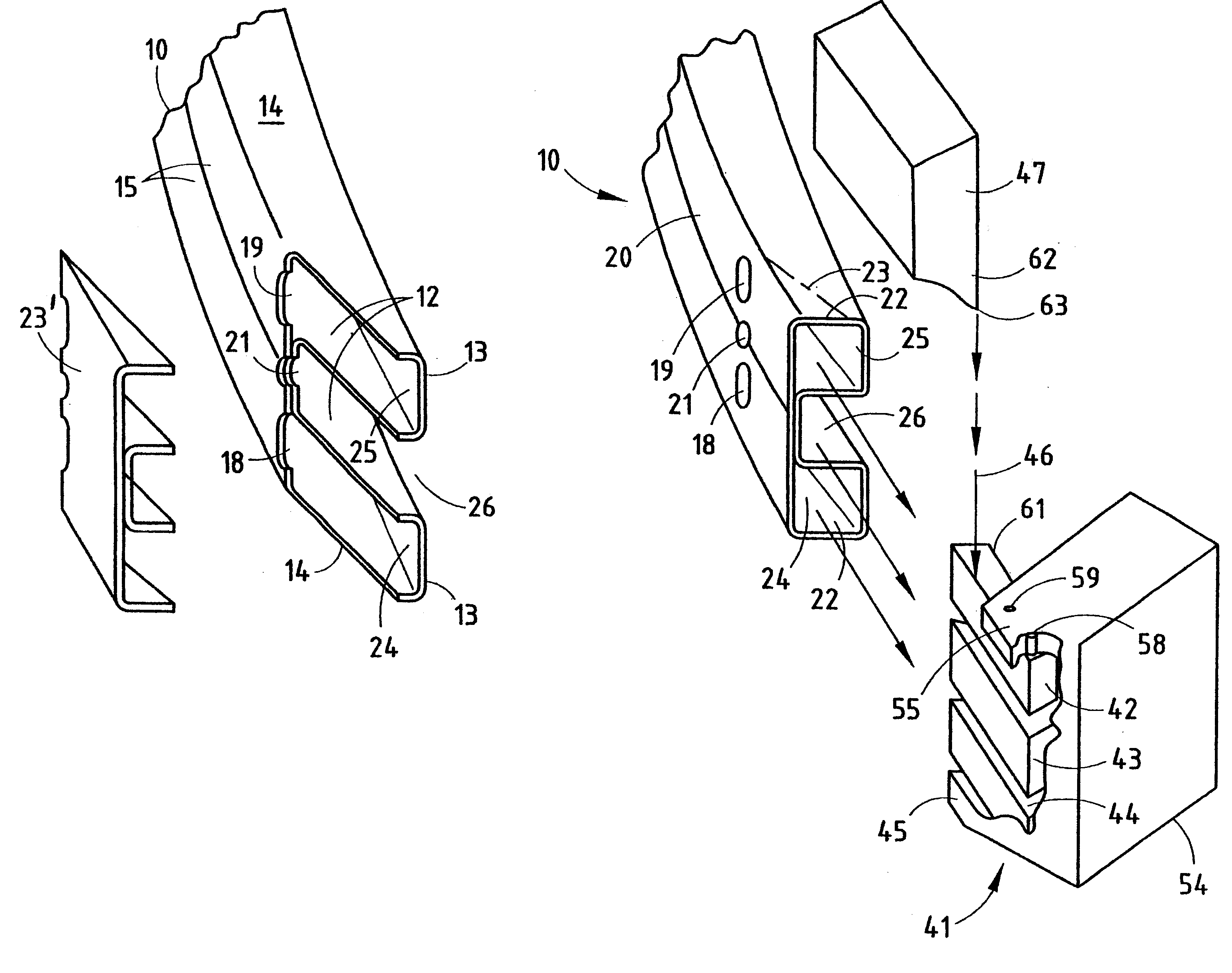
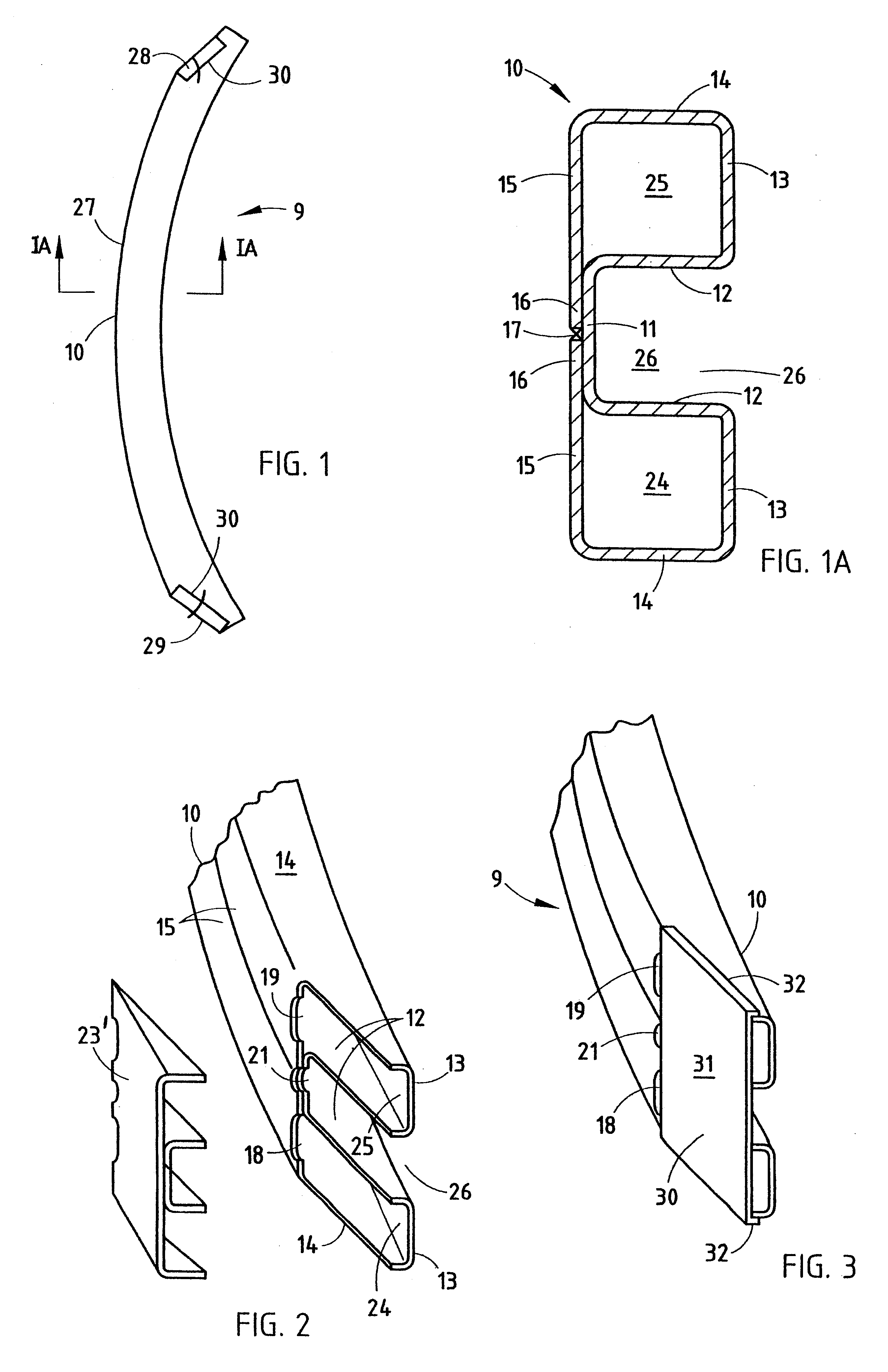
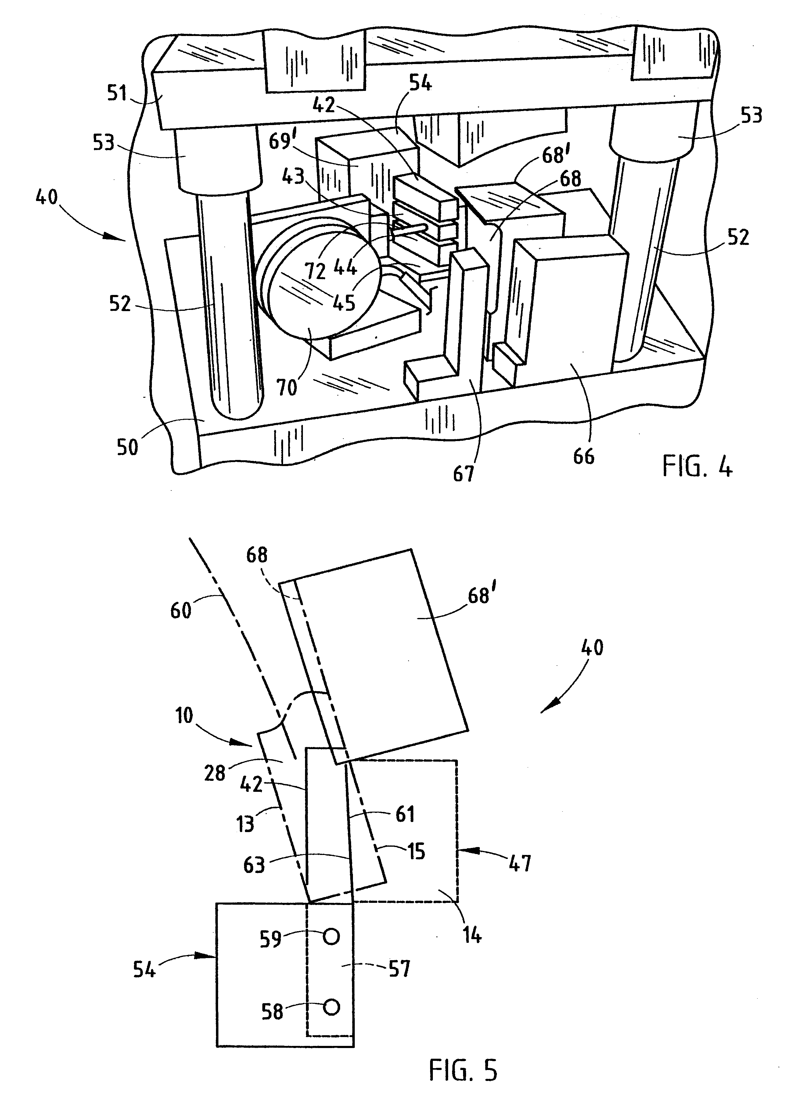
A die apparatus 40 (FIG. 7) includes a lower first die 41 configured to telescopingly engage an end section of a tubular bar 10, such as is used for manufacturing a B-shaped vehicle bumper bar 9 (F...


PUM

PropertyMeasurementUnit
Thicknessaaaaaaaaaa
Lengthaaaaaaaaaa
Angleaaaaaaaaaa

Abstract

A die apparatus includes a first die configured to telescopingly engage an end section of a tubular bar, including one or more "floating" mandrels configured to extend into cavities of the tubular bar, and further including a stationary die member spaced from the mandrel(s). The mandrel(s) and the stationary die member include angled cutting edges that are aligned so that the cutting edges are engageable from a single transverse direction. The mandrel(s) is movably supported on the first die to float parallel the single direction toward and away from the stationary die member. A cutting die has a shearing punch configured to move along the single direction to sequentially engage the angled cutting edges to shear off an angled portion of the end section. The die apparatus is optimally designed for use with a rollformed swept tubular bumper bar having a B-shape and that has walls forming first and second tubular sections that define first and second cavities, with the walls further defining a third cavity between the first and second cavities. In such a die apparatus, the first die includes first, second, and third mandrels configured to extend into the first, second, and third cavities, respectively, of the B-bumper. A method related to the above apparatus is also disclosed.

Description

The present apparatus relates to a die apparatus for cutting angles onto end sections of a vehicle bumper bar made from high strength steel, where the bumper bar has tubular sections extending longitudinally along its length.Recently, novel rollforming apparatuses and methods were patented for forming high strength swept tubular vehicle bumpers. For example, see U.S. Pat. Nos. 5,092,512; 5,104,026; 5,395,036; and 5,454,504. Bumpers made by these apparatuses and methods typically have the advantage of a lower weight and greater strength-to-weight ratio than conventionally stamped bumper bars, and further their manufacturing cost is typically lower or at least very competitive with processes for stamping conventional bumpers for high volume runs. These bumper bars have a continuous curvilinear sweep well-suited for vehicles having an aerodynamic appearance, such as vehicles having rounded front corners.However, vehicle manufacturers have recently designed bumper bars with a compound a...

Claims


Application Information

Patent Timeline
IPC IPC(8): B23D21/02B23P15/00B23D21/00
CPCB23D21/02B23P15/00E04C2003/0456Y10T83/04Y10T83/0596Y10T83/384Y10T83/395Y10T83/748
Inventor STURRUS, PETERHEINZ, RICHARD D.BRIGGS, KIRK W.
Owner SHAPE CORP
Why Eureka
Try Eureka