Thermally efficient computer incorporating deploying CPU module

a cpu module and computer technology, applied in the field of portable computers, can solve the problems of increasing the size of portable computers, reducing battery life, and combining all of them into a single unit, and achieves the effects of convenient transportation, efficient cooling, and convenient separability

Inactive Publication Date: 2001-06-05
SPECULATIVE
View PDF48 Cites 57 Cited by
  • Summary
  • Abstract
  • Description
  • Claims
  • Application Information

AI Technical Summary

Benefits of technology

(k) to provided a computer whereby the major heat producing integrated circuits are contained in a thin, planar module that is easily separable and positioned vertically for efficient cooling of the said components.
(l) to provide a portable computer that can use faster, and thus hotter, CPUs and other integrated circuits, and still be contained in a small enough package to be easil

Problems solved by technology

Unfortunately, there is a problem combining all of these components into a single, small enclosure.
The combination of high performance, high thermal output components, and a fan to cool them, add up to an increase in power drain that reduces battery life.
The size of portable computers is one of the most important performance constraints.
First, the location of the motherboard is in the base, not in a mechanically and thermally separate module.
This radiator substantially increases the footprint of the computer and is therefore undesirable in a portable or desktop version where desk space is highly valued. FIG. 10 of Hatada et al shows an auxiliary radiator that is able to rotate away from the flat-panel display so that heat is not transferred to the display.
Thus, the base cannot be effectively sealed from the intrusion of foreign objects, dust, or spilled liquids.
These configurations are not viable for several reasons.
First, consumers demand the maximum computing power in the smallest package, thus, laptop and notebook computers are under tight size constraints.
Moreover, in this configuration with the motherboard in close proximity to the flat-panel display, the uneven, high temperatures on the motherboard will be transferred to the flat-panel display causing irregularities in display contrast that could make the display unreadable.
In fact, a fa

Method used


Image

  • Thermally efficient computer incorporating deploying CPU module
  • Thermally efficient computer incorporating deploying CPU module
  • Thermally efficient computer incorporating deploying CPU module

Examples


Embodiment Construction

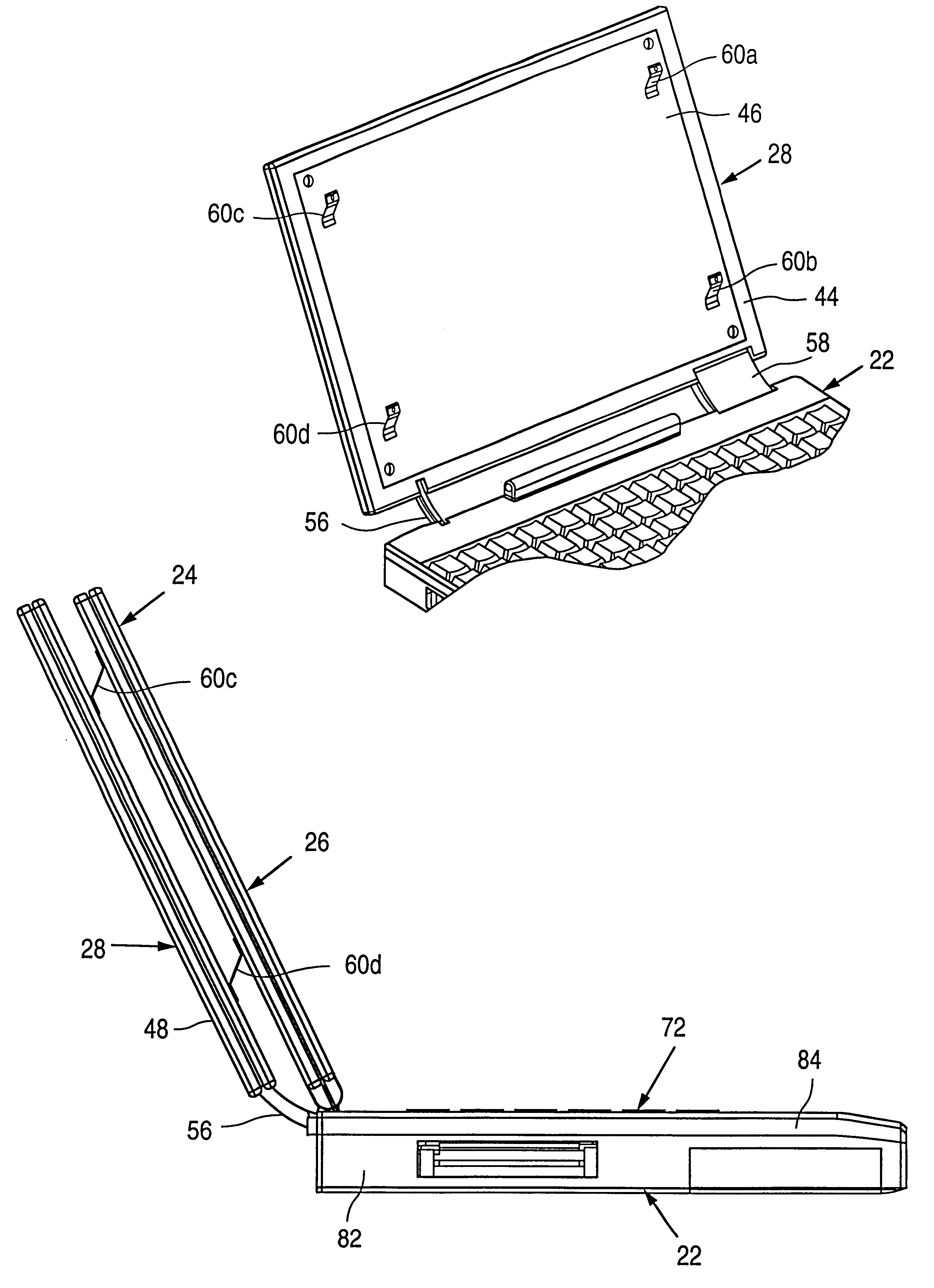
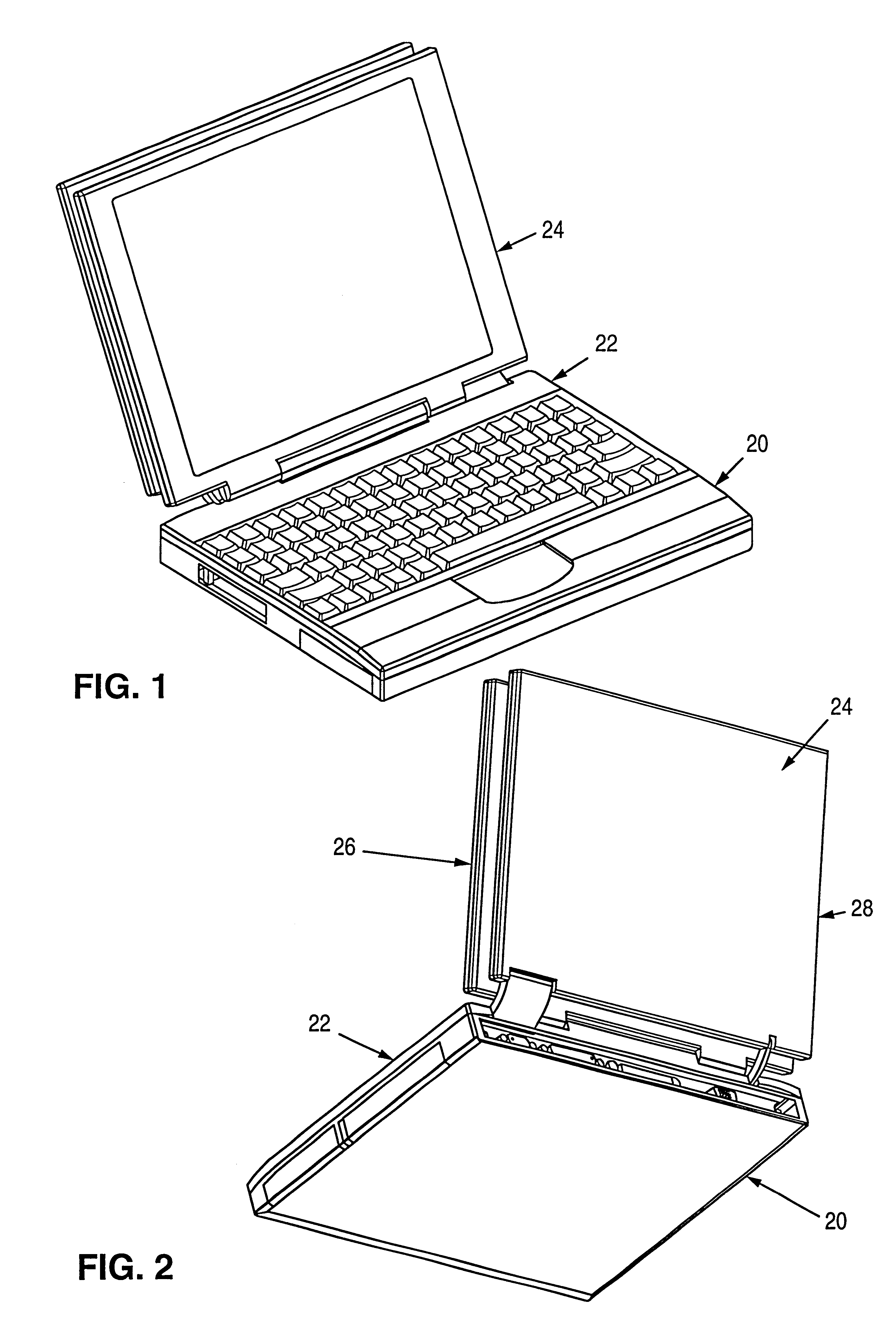
Referring to the drawings, particularly FIGS. 1 and 2, a flat-panel display computer 20 is illustrated according to the present invention and is seen to generally include a base assembly 22 pivotally mounted to a lid assembly 24. As seen in FIGS. 6 and 7, lid assembly 24 generally includes a display module sub-assembly 26 and a CPU module sub-assembly 28.

As seen in FIGS. 6, 7, and 9, base assembly 22 houses a hard disk drive 62, a media bay 64, a plurality of input / output connectors 66, a connector board 68, a PCMCIA module 70, a keyboard sub-assembly 72, a battery pack 74, and a track pad 76. Track pad 76 is a touch-sensitive pointing device used to control the on-screen cursor. These components are contained by a base bottom cover 82 and a base top cover 84. Base bottom cover 82 and base top cover 84 are arranged in a clam-shell configuration.

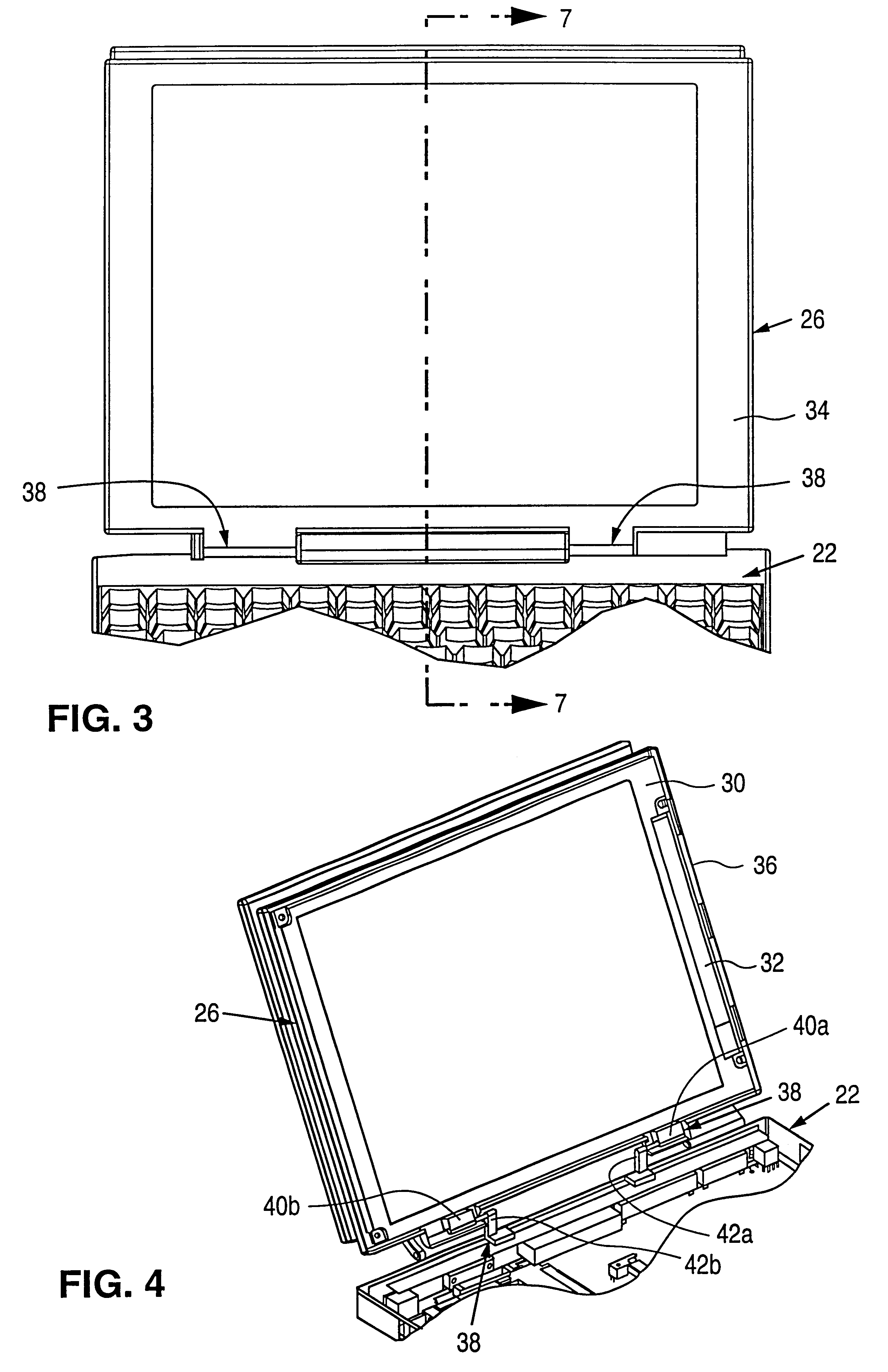
Display module sub-assembly 26 is generally comprised of a display bezel 34 and a display rear cover 36 which are arranged in a clam-shell f...


PUM


Abstract

A portable computer with a base (22) containing media, batteries, and keyboard, with the a CPU 52 and main PCB 50 located in a planar CPU module (28) separate from and behind the flat-panel display module (26), mechanically connected to the display module (26) with a deployment mechanism, and functionally connected to the display module (26) and base (22) by a base flexible circuit (78). The CPU module contains a heat-spreading front cover 46 facing the display module 26, and thermally connected to hot components on the main PCB 50. The translating mechanism operates such that when the display module (26) is closed, the CPU module (28) is adjacent to the display module (26), and when the display module (26) is open, the CPU module (28) is positioned with a gap between the it and the display module (26).

Description

BACKGROUND--FIELD OF INVENTIONThis invention relates generally to the field of portable computers, and more specifically to a design for laptop and notebook computers wherein the CPU and motherboard is contained in a substantially planar module that mechanically separates away from a display module when the computer is being used.1. DefinitionsThe term portable computer includes laptops and notebook computers, and some Personal Digital Assistants. Typically, these computers have a flat-panel display connected to a base by a hinge. The display is shut for transport or storage, and rotated open for use. The base may contain an integral or removable keyboard on the top surface, storage media, batteries, and other components. A portable computer may also feature other user-interface systems, such as a pen-based interface, instead of, or in addition to, a keyboard.CPU module is defined as a housing containing a substantially planar printed-circuit board or assembly of boards, generally i...

Claims


Application Information

Patent Timeline
IPC IPC(8): G06F1/16G06F1/20
CPCG06F1/1615G06F1/1616G06F1/1626G06F1/1632G06F1/1637G06F1/1681G06F1/1683G06F1/20G06F1/203G06F2200/201
Inventor JANIK, CRAIG M.BOYLE, DENNIS J.MONGAN, RYAN H.SHAWVER, MICHAEL J.
Owner SPECULATIVE
Why Eureka
Try Eureka