Liquid delivery system comprising upstream pressure control means

a liquid delivery system and upstream pressure control technology, applied in the direction of chemical vapor deposition coating, steam generation using steam absorption, combustion air/fuel air treatment, etc., can solve the problem of difficult control of the stoichiometry of the deposited films of such decomposition-susceptible reagents, the impracticality of cvd reactor vapor phase delivery, and the reactive and volatile nature of desirable cvd reagents

Inactive Publication Date: 2001-06-12
ENTEGRIS INC
View PDF1 Cites 34 Cited by
  • Summary
  • Abstract
  • Description
  • Claims
  • Application Information

AI Technical Summary

Problems solved by technology

Desirable CVD reagents therefore are fairly reactive and volatile.
Unfortunately, for many of the refractive materials described above, volatile reagents do not exist.
In many cases, the source reagents are solids whose sublimation temperature may be very close to the decomposition temperature, in which case the reagent may begin to decompose in the lines before reaching the reactor, and it therefore is very difficult to control the stoichiometry of the deposited films from such decomposition-susceptible reagents.
In other cases, the CVD reagents are liquids, but their delivery into the CVD reactor in the vapor phase has proven impractical because of problems of premature decomposition or stoichiometry control.
In other cases, the CVD reagents are liquids, but their delivery into the CVD reactor in the vapor phase has proven difficult because of problems of premature decomposition or stoichiometry control.
This deficiency is an important issue in the operation of CVD processes that use thermally unstable solid source precursors which undergo significant decomposition at conditions needed for sublimation.
1) Reactive impurities in either the precursor or in the carrier gas decompose at the vaporizer temperatures.
2) Spatial and t

Method used


Image

  • Liquid delivery system comprising upstream pressure control means
  • Liquid delivery system comprising upstream pressure control means
  • Liquid delivery system comprising upstream pressure control means

Examples


Embodiment Construction

The disclosures of the following patent applications and patents are hereby incorporated herein by reference in their entirety: U.S. Pat. No. 5,711,816 issued Jan. 27, 1998; U.S. patent application Ser. No. 08 / 402,142 filed Mar. 10, 1995 in the name of Peter C. Van Buskirk; U.S. Pat. No. 5,741,363 issued Apr. 21, 1998; International Patent Application No. PCT / US94 / 02512 filed Mar. 7, 1994 and designating therein the United States as a Designated State; U.S. Pat. No. 5,536,323 issued Jul. 16, 1996; U.S. application Ser. No. 08 / 927,134 filed Aug. 7, 1992; U.S. Pat. No. 5,204,314; and U.S. application Ser. No. 07 / 549,389 filed Jul. 6, 1990.

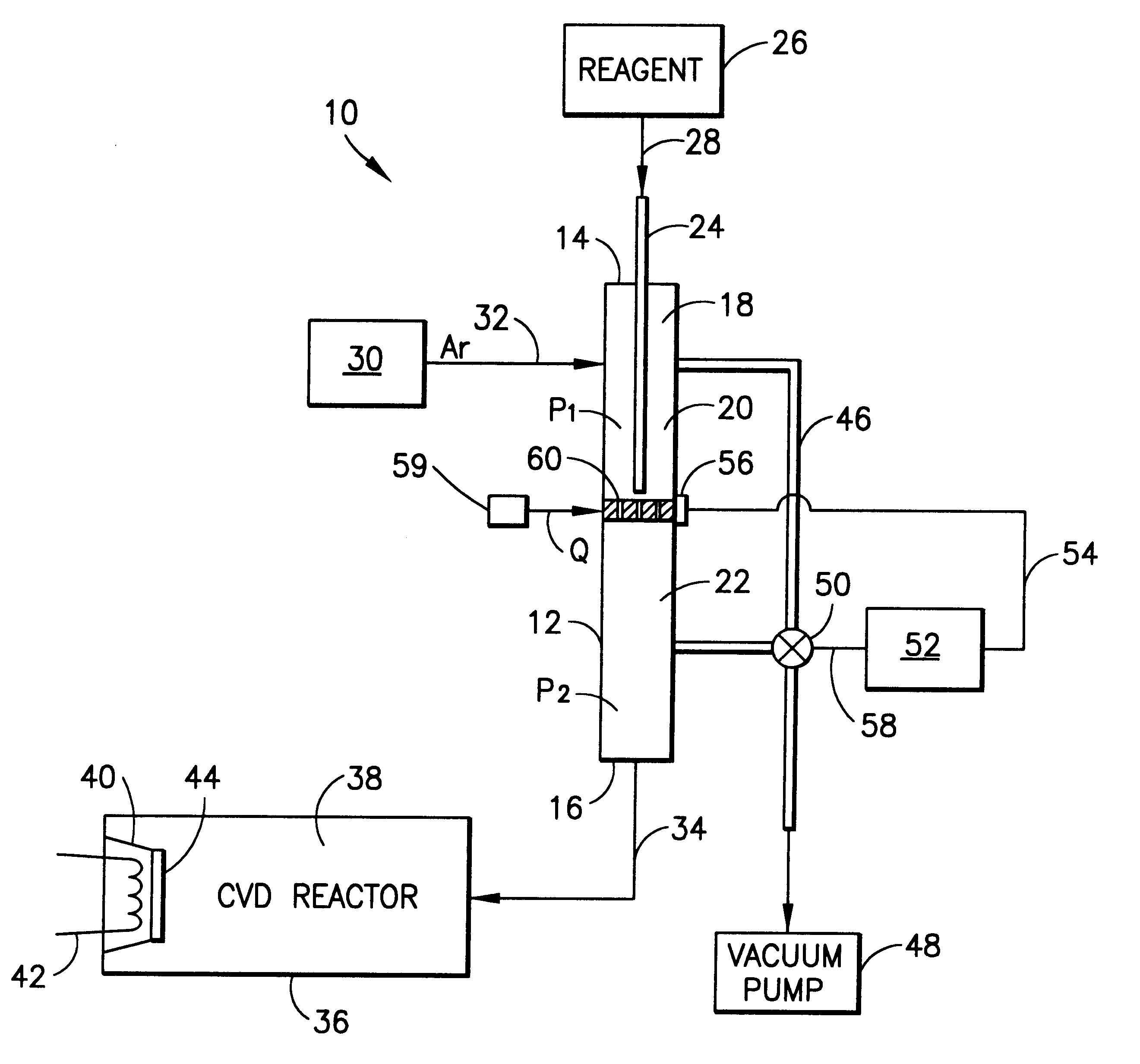
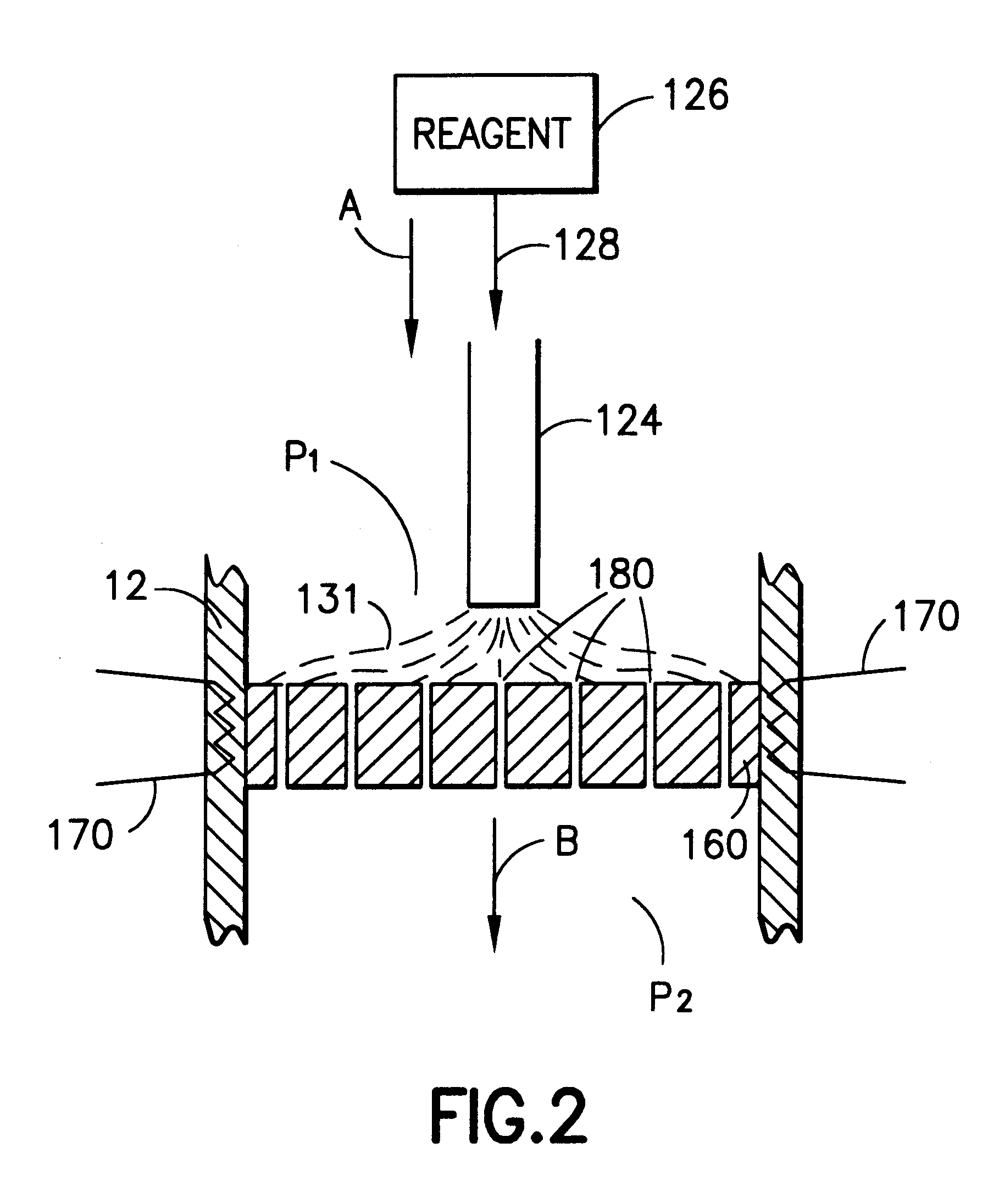
The present invention relates to a liquid delivery and vapor deposition system, and more specifically to a liquid delivery system in which fluid pressure upstream of a porous vaporization element which acts as a fluid flow restriction or impedence element is controllable so that the pressure is modulated and maintained within allowable operating limi...


PUM

PropertyMeasurementUnit
Lengthaaaaaaaaaa
Diameteraaaaaaaaaa
Diameteraaaaaaaaaa

Abstract

A liquid delivery system (10) for vaporization of a liquid pecursor to form precursor vapor for transport to a deposition zone (36). The system includes a vaporization chamber (12), a porous vaporization element (60) positioned in the vaporization chamber (12) to define an upstream portion (20) of the vaporization chamber (12) upstream of the porous vaporization element (60), and a downstream portion (22) of the vaporization chamber (12) downstream of the porous vaporization element (60) therein, a vaporization element heater (59), a liquid precursor supply (26) for introducing liquid precursor to the vaporization element (60) for vaporization thereof, a precursor vapor discharge (16) from the chamber, and means (46, 48, 50, 52, 54, 56 and 58) for diverting at least a part of the fluid in the upstream portion of the vaporization chamber (12) past the porous vaporization element (60), to stabilize fluid pressure in the upstream portion of the vaporization chamber (12) under conditions tending to perturb such fluid pressure.

Description

DESCRIPTION1. Field Of The InventionThis invention relates generally to an apparatus and method for vaporization of a liquid precursor for transport to a deposition zone, e.g., a chemical vapor deposition (CVD) reactor. More particularly, the present invention relates to a liquid delivery system of such type, in which the pressure upstream of the vaporization means is controllably maintained at a level commensurate with highly efficient operation of the liquid delivery system.2. Description Of The Related ArtIn the formation of thin films, layers and coatings on substrates, a wide variety of source materials have been employed. These source materials include reagents and precursor materials of widely varying types, and in various physical states. To achieve highly uniform thickness layers of a conformal character on the substrate, vapor phase deposition has been used widely as a technique. In vapor phase deposition, the source material may be of initially solid form which is sublime...

Claims


Application Information

Patent Timeline
IPC IPC(8): C23C16/448C23C16/52
CPCC23C16/448C23C16/4483C23C16/52
Inventor BHANDARI, GAUTAMBRESTOVANSKY, DENNIS F.
Owner ENTEGRIS INC
Why Eureka
Try Eureka