Information input device

a technology of information input and input device, which is applied in the field of information input device and, can solve the problems of inability to determine distance, inability to read accurate images that correspond to scanning speed, and difficulty in maintaining firm contact with images by operators

Inactive Publication Date: 2001-06-19
SEIKO EPSON CORP
View PDF16 Cites 19 Cited by
  • Summary
  • Abstract
  • Description
  • Claims
  • Application Information

AI Technical Summary

Problems solved by technology

However, as explained above, it is not always easy for the operator to maintain firm contact with the image while moving the roller; in some cases the roller might be moved while it is not in contact with the image.
Since the roller does not rotate if it is not in contact with the image while being moved, distance cannot be determined.
Consequently, an accurate image that corresponds to the scanning speed cannot be read.
Additionally, frequent use of the scanner may cause wear or damage in the moving area (roller area), rendering the scanner unfit for long-term use.
This results in extremely poor image input efficiency, especially when high-speed computers are used for image processing tasks.
Furthermore, because the amount of image data that can be stored in the buffer is finite, it is not possible to fully utilize the processing capability of the personal computer to which the image input device is connected.
Consequently, the sequentially-performed large buffer fill, full buffer image processing, buffer flush and buffer refill steps constitute an inflexible data bottleneck, which makes it difficult to optimize throughput and task handling for differently-configured computer serving as host for image processing tasks.
A similar problem occurs in scanners in which a character recognition area is connected to the above-mentioned image input unit 20 and image processing unit 30.
Furthermore, the difference (wait time) between this information input processing completion time and the image input time of image input unit 20 becomes proportionally longer as the image input time of image input unit 20 increases, resulting in extremely poor information input efficiency.
Additionally, in such a method, buffer 40 shown in prior art FIG. 18 must be extremely large since it must store all of the corrected image data downloaded during a particular scan event.
However, doing so will result in much wasted wait time for high-speed personal computers, lowering processing efficiency, and preventing optimal utilization of the full processing capability of the personal computer.

Method used


Image

  • Information input device
  • Information input device
  • Information input device

Examples


first embodiment

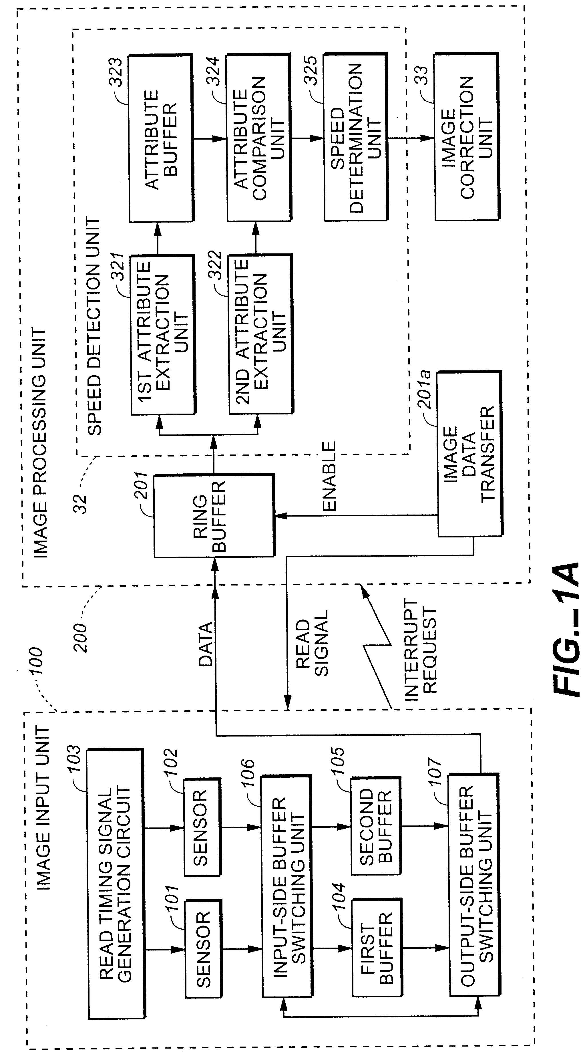
An overview of the operation of an information input device possessing such a configuration is as follows. Problems such as distortion in the image data read by image input unit 100 are corrected by image processing unit 200. (Processing operation up to this point is identical to that explained in the first embodiment). After this corrected image data is stored in the second ring buffer 400, character recognition unit 300 reads the corrected data from the second ring buffer 400, uses character extraction unit 301 to extract characters from the image data, and uses character code generation unit 302 to generate character codes matching those characters.

This overall operation is further explained with reference to the flow chart shown in FIG. 7.

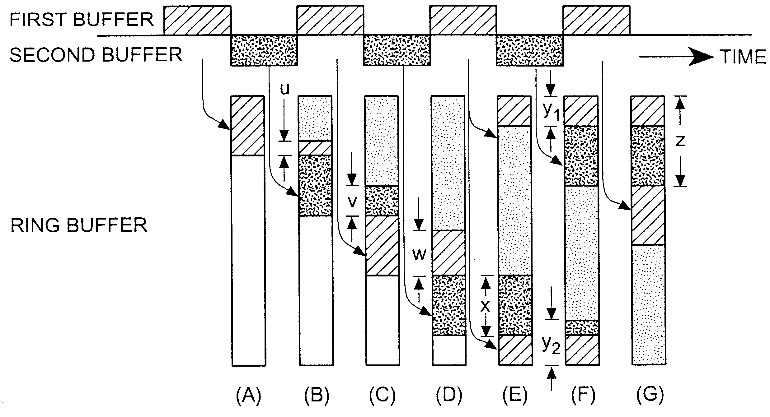
In FIG. 7, assuming buffer 104 is to be filled first, control begins at step s21 within the image input area and remains until a preset amount of image data has been placed in buffer 104. Thereafter, control passes to step s22, in which buffer ...

second embodiment

Meanwhile, at step s25, the image input area of the second embodiment is filling the contents of buffer 105 with newly acquired image data. As before, processing remains at this step until the image input area perceives the second buffer 105 to be full enough for image data transfer to resume. Thereafter, control passes to step s26, where buffer switching complementing the switches made in step s22 is performed. At step s27, the first buffer 104 begins receiving image data, and at the same time an image data transfer interrupt request is sent to image processing unit 200. Image processing unit 200 receives this interrupt request and now accepts the image data from the second buffer 105. This process is repeated until all scanned image data has been received. Note that the image data transfer interrupt request is also issued to character recognition unit 300. This point will be explained further below.

Image processing unit 200 interrupts the image correction it has been performing wh...


PUM


Abstract

An image-scanning device which includes an image input unit possessing an image sensor unit that reads images such as characters and graphics on a manuscript illuminated by a light source, transfers the image data corresponding to the read data in a specified size after issuing an image data transfer interrupt request; and an image processing unit possessing a ring buffer that stores the image data being sent from the image input unit on a specified data size basis in specified areas, and which performs image correction on the image data stored in this ring buffer between image data transfer interrupt requests from the image input unit.

Description

1. Field of the InventionThis invention relates to an information input device and method that scans in character and graphical-based information contained in printed form and converts this information into computer-readable image data or character codes.2. Description of the Related ArtThe microcomputer revolution of the past decade has brought about universal access to processing power and computing options once reserved exclusively for expensive mainframe architectures. And, as personal computer development advances at an ever increasing pace, so too does the variety and adaptation of their use in the marketplace. This has spurred a rapid introduction of intelligent, microcontroller-driven consumer products mentioned only in science fiction novels just a few years before.One of the most active trends in contemporary computing has been in the field of document processing, and more particularly, converting printed information into electronic form. Peripheral devices known as "handh...

Claims


Application Information

Patent Timeline
Patent Type & Authority Patents(United States)
IPC IPC(8): H04N1/047H04N1/193H04N1/107H04N1/191G06T1/60H04N1/00G06K9/20
CPCH04N1/047H04N1/107H04N1/193H04N2201/04703H04N2201/04787H04N2201/04734H04N2201/04743H04N2201/02439H04N2201/04794
Inventor AOKI, MIKIONITTA, TAKASHI
Owner SEIKO EPSON CORP
Why Eureka
Try Eureka