Preamplifier and protection circuit for an ultrasound catheter

Inactive Publication Date: 2001-06-26
BOSTON SCI SCIMED INC
View PDF9 Cites 16 Cited by
  • Summary
  • Abstract
  • Description
  • Claims
  • Application Information

AI Technical Summary

Benefits of technology

Preferably, the output impedance of the preamplifier matches the characteristic impedance of the transmission line. In addition, tuning circuitry is preferably coupled to the rotatable transducer to reduce the imaginary component of the impedance of the transducer, thus increasing the efficiency and bandwidth of the transducer.

Problems solved by technology

Because the signals are of small amplitude and must travel through 5 to 6 feet of transmission line before being processed, noise received during transmission in the transmission line presents a serious problem.
In addition to the noise added by the transmission line, intravascular ultrasound systems face other problems.
Prior art ultrasound systems with rotatable transducers have failed to address the problem caused by the transmission line noise.
Although the system disclosed by Andou et al. possesses a preamplifier, this preamplifier is located at the proximal end of the cable so that it cannot improve the signal-to-noise ratio before signal transmission through the transmission line.
In addition, a proximally located preamplifier does not simplify tuning or matching of the transducer impedance.

Method used


Image

  • Preamplifier and protection circuit for an ultrasound catheter
  • Preamplifier and protection circuit for an ultrasound catheter
  • Preamplifier and protection circuit for an ultrasound catheter

Examples


first embodiment

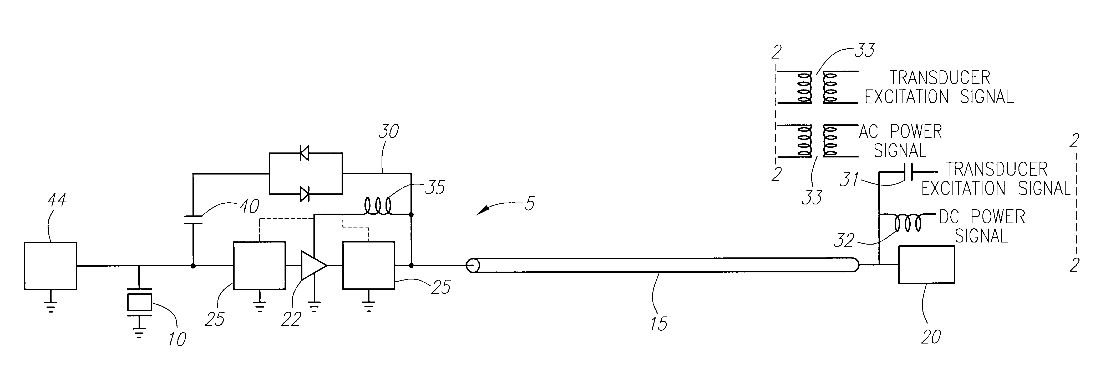
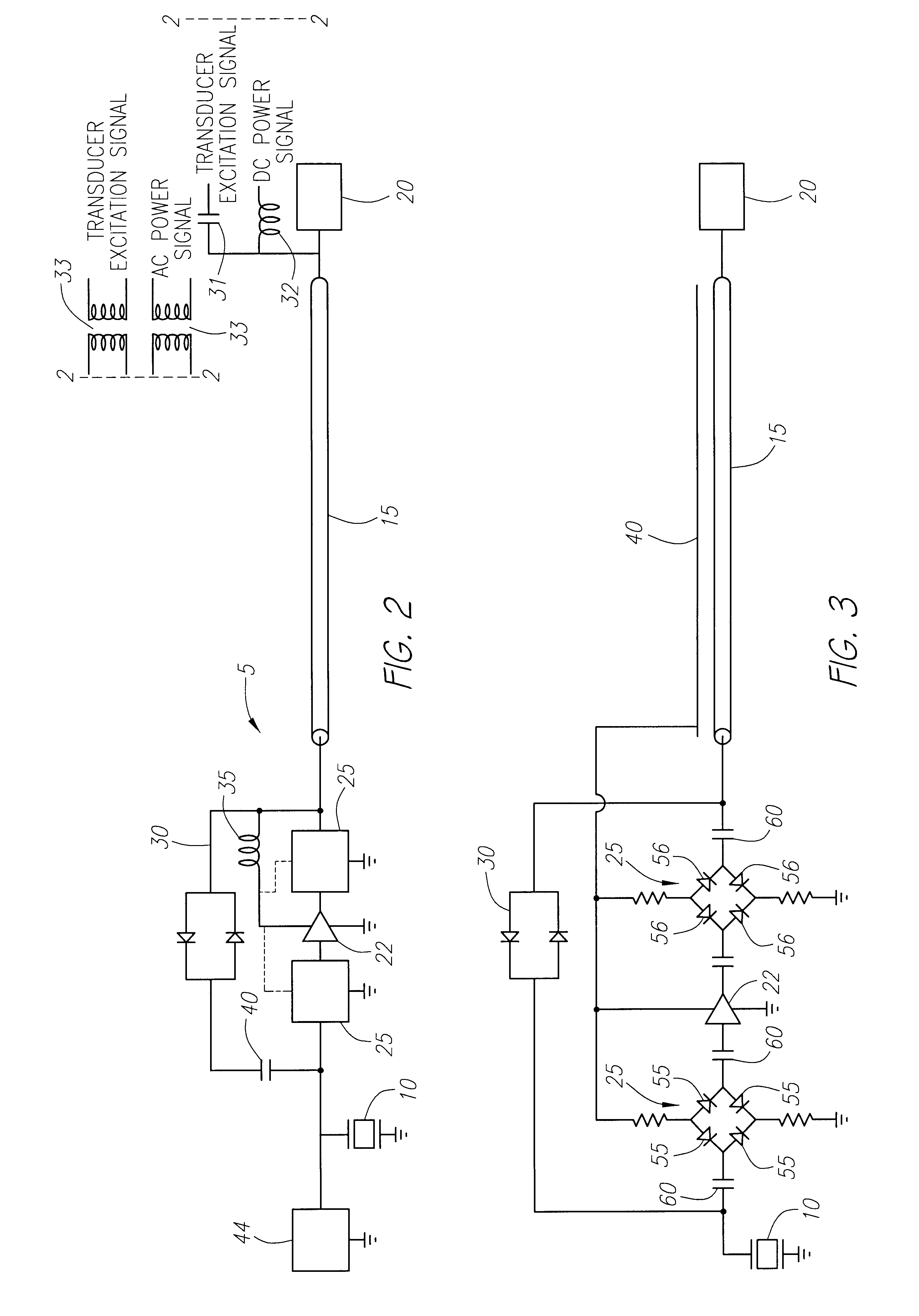
Turning now to FIG. 2, a rotatable transducer 10 couples to the distal end of a transmission line 15 in an ultrasound catheter 5. The transmission line 15 may comprise a coaxial cable, a twisted-wire pair or other suitable means. A preamplifier 22, also coupled to the distal end of the transmission line 15, amplifies a received signal produced by the rotatable transducer 10. Note that the preamplifier 22 will need a DC power signal for proper operation whereas the rotatable transducer requires a transducer excitation signal consisting of, in one embodiment, bipolar high amplitude impulses. The transmission line 15 provides only a single channel for signal transmission. Thus, the ultrasound catheter 5 of the present invention includes three different embodiments in which the two separate signals, the DC power signal and the transducer excitation signal are accommodated. In the first embodiment, illustrated in FIG. 2, the transducer excitation signal and the DC power signal are multip...

second embodiment

In a second embodiment, illustrated in FIG. 3, the transducer excitation signal and the DC power signal are not multiplexed onto the transmission line 15. Instead, the transmission line 15 carries only the transducer excitation signal and received echo signals. The DC power signal transmits through an external drive cable 40. As illustrated, the external drive cable 40 may consist of only a single conductor so it shares the outer conductor of transmission line as its ground, or it may have its own ground. The preamplifier 22 couples to the external drive cable 40 to provide the DC power signal. The rotatable transducer 10 couples to the transmission line 15 to receive the transducer excitation signal.

third embodiment

In a third embodiment, illustrated in FIG. 4, a DC power signal is not externally supplied through a drive cable 40 or through multiplexing onto the transmission line 15. Instead, the ultrasound catheter 5 generates the DC power signal through rectification of the transducer excitation signal in a rectifier circuit 45. The rectifier circuit 45 preferably couples to the transducer excitation signal at the output of the preamplifier 22 to assure the strongest signal possible for rectification. A suitable rectifier circuit 45, illustrated in FIG. 5, comprises a series connected resistor 46, diode 4 and capacitor 48. The rectified DC power signal, denoted as Vcc, is stored across the capacitor 48. A zener diode 49, arranged in parallel with the capacitor 48, regulates the DC power signal. Those of ordinary skill in the art will appreciate that many alternate circuits could be constructed to perform similarly to the circuit illustrated in FIG. 5.

The preamplifier 22 receives the DC power ...


PUM


Abstract

An ultrasound catheter wherein a rotatable transducer couples to the input of a preamplifier. Protection circuits at the input and output of the preamplifier protect the preamplifier from the transducer excitation signal. The preamplifier couples to the distal end of a transmission line. In an alternate embodiment, at least one switch responds to the presence of the transducer excitation signal by coupling the transducer excitation signal to the rotatable transducer and protecting the preamplifier from the transducer excitation signal. The at least one switch responds to the absence of the transducer excitation signal by coupling a received signal produced by the rotatable transducer to the input of the preamplifier. The at least one switch further responds to the absence of the transducer excitation signal by coupling the output of the preamplifier to the distal end of the transmission line.

Description

FIELD OF THE INVENTIONThis invention relates to ultrasound systems. More particularly, this invention relates to an ultrasound catheter having a preamplifier and protection circuitry.BACKGROUND OF THE INVENTIONIntravascular ultrasound systems allow clinicians to image within coronary arteries and other vessels. Typically, the clinician will route a guidewire from the femoral artery, through the aorta and into the coronary arteries. When satisfied with the location of the guidewire, the clinician guides an ultrasound catheter having a transmission line coupled to a rotating transducer at its distal end along the guidewire to the coronary arteries. As illustrated in FIG. 1, signals produced by the transduce 10 must travel through the transmission line 15 before being processed in the signal processor 20. Because the signals are of small amplitude and must travel through 5 to 6 feet of transmission line before being processed, noise received during transmission in the transmission line...

Claims


Application Information

Patent Timeline
IPC IPC(8): A61B8/12
CPCA61B8/12A61B8/4461
Inventor MOORE, THOMAS C.SUORSA, VEIJOMASTERS, DONALD
Owner BOSTON SCI SCIMED INC
Why Eureka
Try Eureka