Reaction force isolation system for a planar motor

a technology of reaction force isolation and planar motor, which is applied in the direction of motor/generator/converter stopper, multiple dynamo-motor starters, machines/engines, etc., can solve the problems of wafer misalignment, vibration in the system, and alignment errors

Inactive Publication Date: 2001-06-26
NIKON CORP
View PDF19 Cites 50 Cited by
  • Summary
  • Abstract
  • Description
  • Claims
  • Application Information

AI Technical Summary

Problems solved by technology

Several factors may cause alignment errors.
Vibrations of the structures within the photolithographic system could cause misalignment of the wafer.
The reaction forces between the moving portion and fixed portion of the planar motor are known to induce vibrations in the system.

Method used


Image

  • Reaction force isolation system for a planar motor
  • Reaction force isolation system for a planar motor
  • Reaction force isolation system for a planar motor

Examples


Embodiment Construction

The following description is of the best-contemplated mode of carying out the invention. This description is made for the purpose of illustrating the general principles of the invention and should not be taken in a limiting sense. The scope of the invention is best determined by reference to the appended claims.

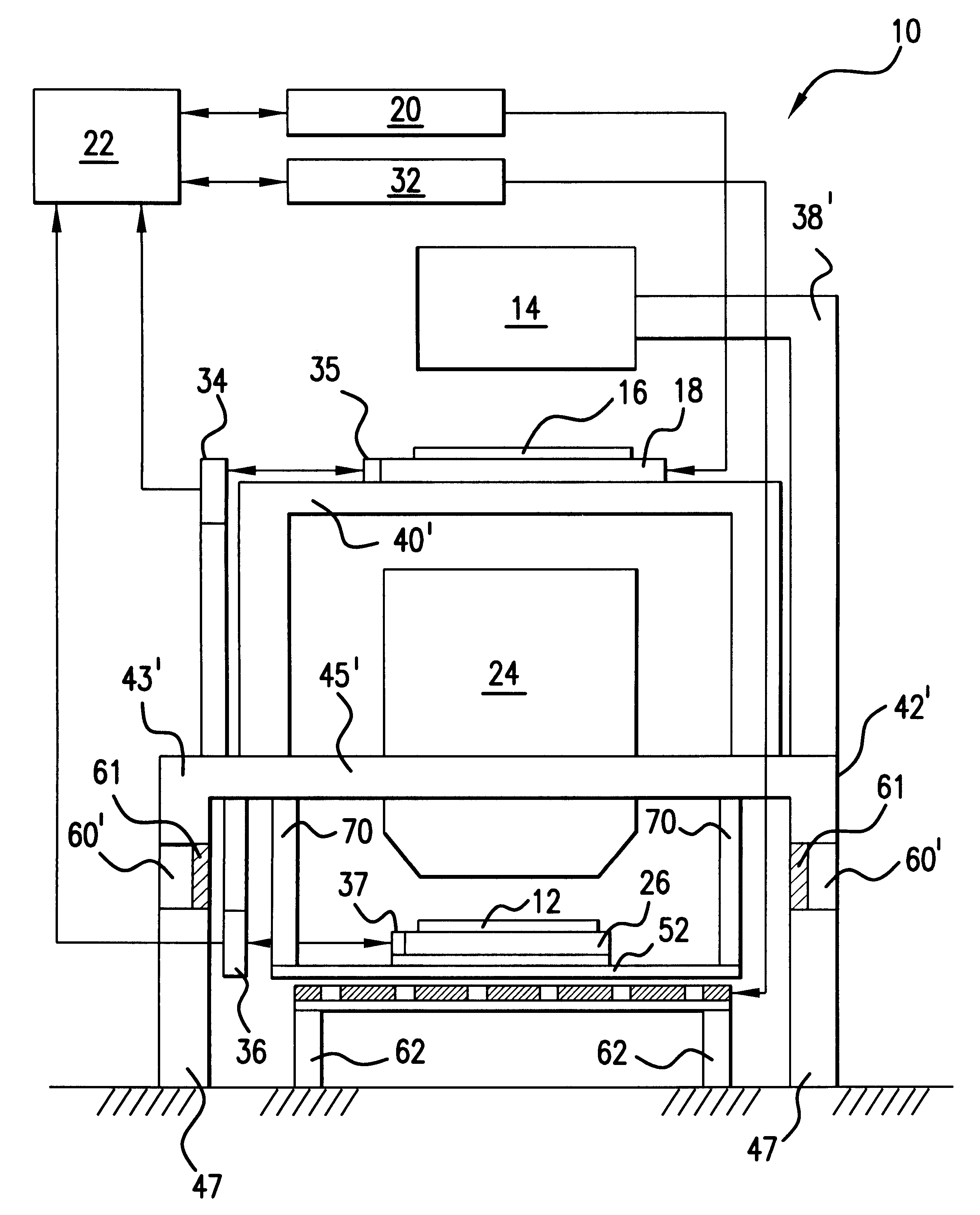
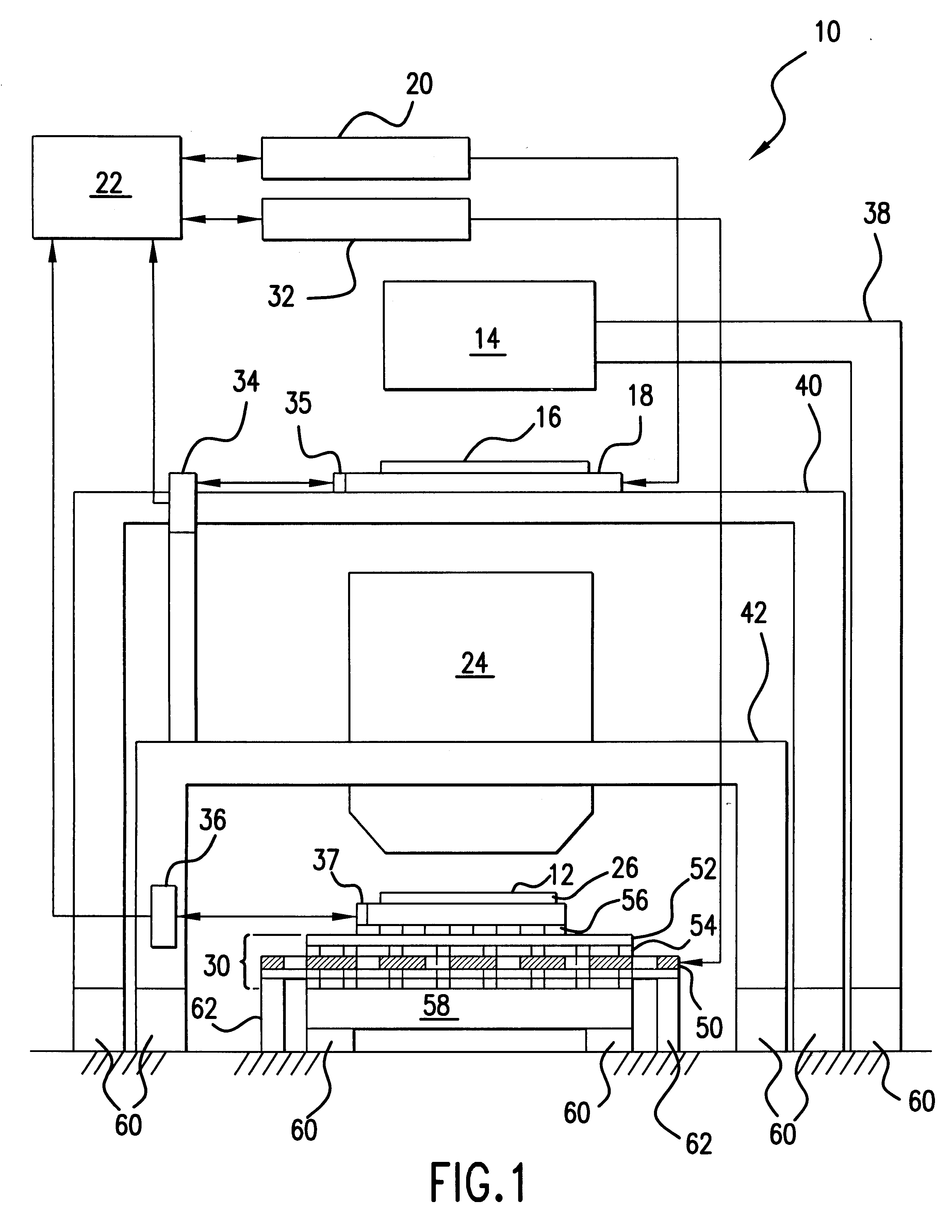
To illustrate the principles of the present invention, the isolation of vibrations induced by reaction forces generated by a planar motor is described in reference to a scanning-type photolithography system for substrate processing. However, it is understood that the present invention may be easily adapted for use in other types of exposure systems for substrate processing (e.g., projection-type photolithography system or electron-beam (EB) photolithography system disclosed in U.S. Pat. No. 5,773,837) or other types of systems (e.g. pattern position measurement system disclosed in U.S. Pat. No. 5,539,521, wafer inspection equipment, machine tools, electron beam, microscope) f...


PUM

PropertyMeasurementUnit
reaction forceaaaaaaaaaa
non-magneticaaaaaaaaaa
bendingaaaaaaaaaa

Abstract

The present invention provides a structure for isolating the reaction forces generated by a planar motor. Specifically, the fixed portion of the reaction motor, which is subject to reaction forces, is structurally isolated from the rest of the system in which the planar motor is deployed. In accordance with one embodiment of the present invention, the fixed portion of the planar motor is separated from the rest of the system and coupled to ground. The rest of the system is isolated from ground by deploying vibration isolation means. Alternatively or in addition, the fixed portion of the planar motor may be structured to move (e.g., on bearings) in the presence of reaction forces, so as to absorb the reaction forces with its inertia. In a further embodiment of the present invention, the fixed portion of the planar motor and the article to be moved are supported by the same frame, with the fixed portion of the planar motor movable on bearings.

Description

1. Field of the InventionThe present invention relates, in general, to planar motor driven positioning systems, and more particularly to such method and apparatus for positioning and aligning a wafer in a photolithographic system using a planar motor and isolating the system from the reaction forces of the planar motor.2. Related Background ArtVarious support and positioning structures are available for positioning an article for precision processing. For example in semiconductor manufacturing operations, a wafer is precisely positioned with respect to a photolithographic apparatus. In the past, planar motors have been advantageously utilized to position and align a wafer stage for exposure in the photolithographic apparatus. For example, U.S. Pat. Nos. 4,535,278 and 4,555,650 to Asakawa describe the use of planar motors in a semiconductor manufacturing apparatus.A semiconductor device is typically produced by overlaying or superimposing a plurality of layers of circuit patterns on ...

Claims


Application Information

Patent Timeline
Patent Type & Authority Patents(United States)
IPC IPC(8): F16F15/02G03F7/20G12B5/00G03F9/00G12B9/08H01L21/027H01L21/68H02K41/03
CPCF16F15/02G03F7/70358G03F7/70716G03F7/70758G03F7/70833G03F7/709
Inventor HAZELTON, ANDREW J.TANAKA, KEIICHIHAYASHI, YUTAKAITO, NOBUKAZU
Owner NIKON CORP
Why Eureka
Try Eureka