
Wireless broadcast link to remote receiver

a remote receiver and wireless technology, applied in the field of wireless signal transmission systems and apparatuses, can solve the problems of limiting the use of additional speakers or additional receivers, affecting the user's home stereo system or television, and the distance or separation between the remote receiver antenna and the output device is relatively limited,

Inactive Publication Date: 2001-07-03
CONCERT TECH
View PDF13 Cites 193 Cited by
  • Summary
  • Abstract
  • Description
  • Claims
  • Application Information

AI Technical Summary

Benefits of technology

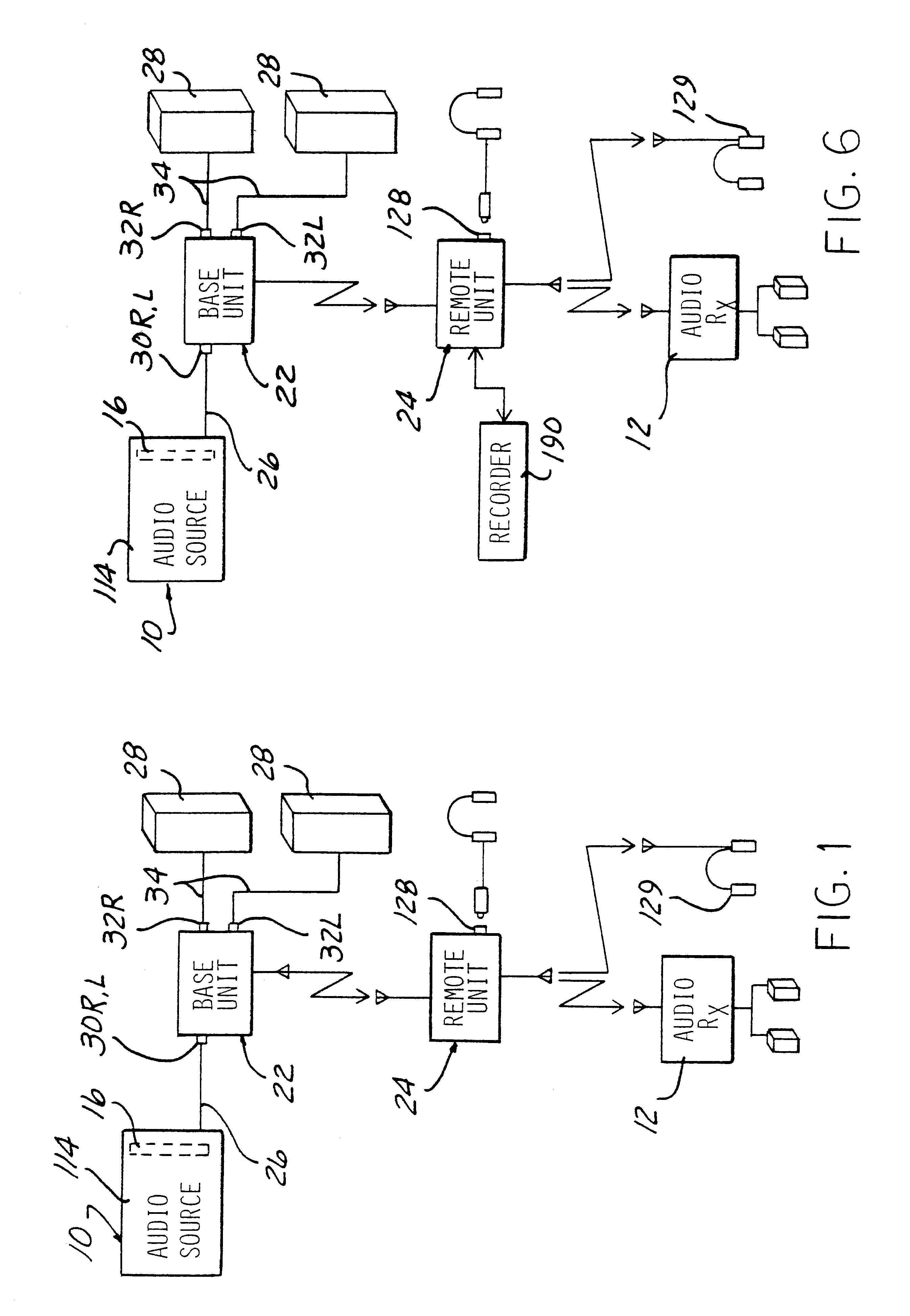
The present inventive apparatus further retransmits a wireless received signal at a remote receiver to a further remote receiver. This expands the range of the present wireless signal transmission apparatus compared to previously devised high frequency signal transmission systems.
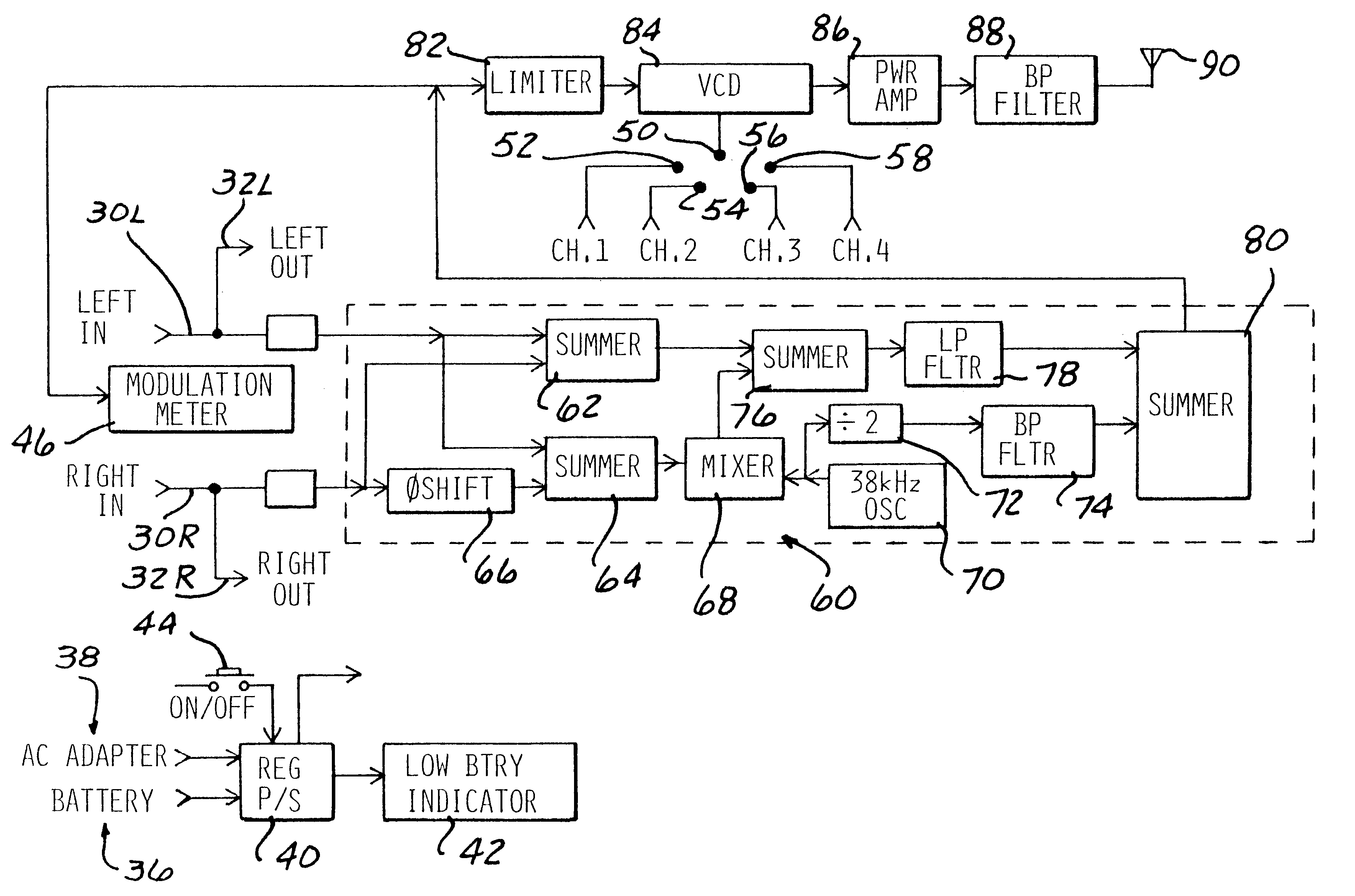
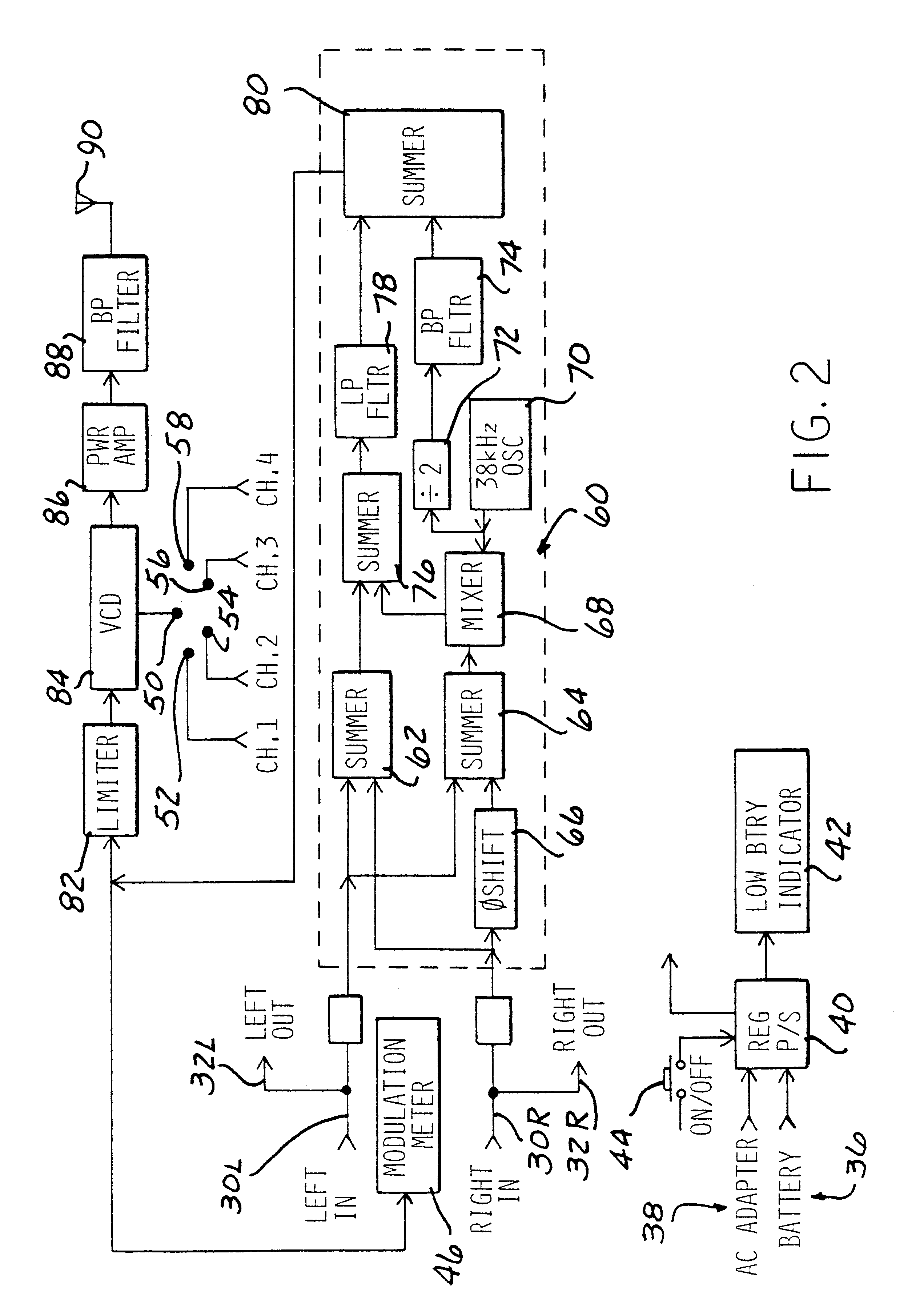
The present apparatus also provides selectable channels in both the transmitter and the receiver to provide excellent signal quality without interference. The present apparatus uniquely converts the high frequency carrier of the first modulated signal from the first transmitter to a lower frequency carrier used in the second modulated signal transmitted from a remote unit containing the first receiver to the further remote receiver without utilizing conventional demodulating and modulation of circuits. This improves the signal to noise quality of the transmitted signal while significantly reducing the cost of the apparatus since less expensive conversion circuits are employed rather than the higher cost modulation and demodulation circuits.

Problems solved by technology

The distance or separation between the remote receiver antenna and the output device is relatively limited due to the low power level signals transmitted at the high carrier frequency.
This small transmission range limits the use of additional speakers or an additional receiver and speakers which may not be located in the same general area as the first transmitter and the output device.
Frequently, however, the audio system or the monitor employed with a computer is not as sophisticated as the user's home stereo system or television.
Further, a user's computer may not be located in the same room or area of a home as the multi-component stereo system or television.

Method used


Image

  • Wireless broadcast link to remote receiver
  • Wireless broadcast link to remote receiver
  • Wireless broadcast link to remote receiver

Examples


Embodiment Construction

Referring now to the drawings, and to FIGS. 1-5C in particular, there is depicted a preferred aspect of the present invention which is described hereafter with reference to the transmission of audio stereo signals from an audio signal source 10 to a remote audio output device 12.

However, it will be understood that the following description of an audio signal embodiment of the inventive high frequency signal transmission apparatus is by example only as the present invention also encompasses the high frequency transmission of video signals and both analog and video signals in either analog or digital format. The source of video signals can include an Internet media broadcast, a cable television signal feed, a television broadcast, the output of a video cassette recorder, etc.

Although the audio source 10 is described hereafter as a computer connected via a modem, not shown, to the Internet for receiving and downloading music or other audio signals from a remote source via conventional ...


PUM


Abstract

A high frequency signal transmission apparatus includes a transmitter for transmitting received signals from a signal source as a modulated signal on a high frequency 900 MHz carrier to a remote receiver. The remote receiver converts the high frequency carrier in at least one conversion step to a lower frequency carrier signal. The lower frequency carrier signal carrying the modulated signal is then converted to another carrier signal and retransmitted as a modulated second signal to another remote receiver capable of demodulating the signal and broadcasting the audio sounds or video images. The oscillators in the transmitter and receiver are selectable to operate at discrete frequencies. Automatic fine tuning control is provided in the receiver to accommodate drift of the oscillator in the receiver. A recorder is coupled to the receiver for temporarily storing a demodulated first signal from the transmitter and then outputting the stored signals to a second transmitter for retransmission to a remote output device.

Description

1. Field of the InventionThe present invention relates, in general, to wireless signal transmission systems and apparatus and, specifically, to wireless transmission system capable of transmitting audio or video signals in either analog or digital format via high frequency carrier signals in the 900 MHZ range and, even more specifically, to wireless signal transmission systems wherein a transmitter coupled to a signal source is linked via a wireless connection to a remote receiver and output device.2. Description of the ArtVarious wireless audio and video signal transmission systems have been devised which transmit audio and / or video signals, such as television signals, radio signals, etc., by a wireless link from a signal source to a signal receiver or output device capable of converting the received signals to audio and / or video sounds.Local wireless television transmission systems which transmit television or radio signals from a local source, such as a television, VCR, radio set...

Claims


Application Information

Patent Timeline
IPC IPC(8): H04B1/16H04N5/38H04B1/38
CPCH04B1/16H04N5/38H04B1/3805
Inventor DRAKOULIS, NIKOPACE, RONALD G.PEDIGO, MICHAEL K.PHILLIPS, RUSSELL A.
Owner CONCERT TECH
Learn More