
Power assisted liposuction and lipoinjection equipment

a technology of liposuction and lipoinjection equipment, which is applied in the field of hand tools, can solve the problems of lumpy surface, tissue tear, and surgery that requires significant effort on the part of surgeons, and achieves the effects of reducing the risk of surgery, reducing and improving the effect of surgical recovery

Inactive Publication Date: 2001-07-10
MICROAIRE SURGICAL INSTR
View PDF62 Cites 57 Cited by
  • Summary
  • Abstract
  • Description
  • Claims
  • Application Information

AI Technical Summary

Benefits of technology

It is another object of this invention to provide a hand held, power liposuction tool which drives an external cannula, and which has a form fitting configuration for the surgeon's hand which allows neat storage and selective disengagement of the aspiration tubing, ease in monitoring clogging in the aspiration tube, and simple and direct control of the cannula drive speed.
It is yet another object of this invention provide a power assisted, reciprocating cutting tool with a suction control feature which allows for adjusting the cutting and aspiration conditions for different tissues.
It is still another object of this invention to provide for a filtering system to be used in conjunction with a power assisted liposuction tool which retains aspirated fat tissue for ease in washing and re-use in lipoinjection procedures.
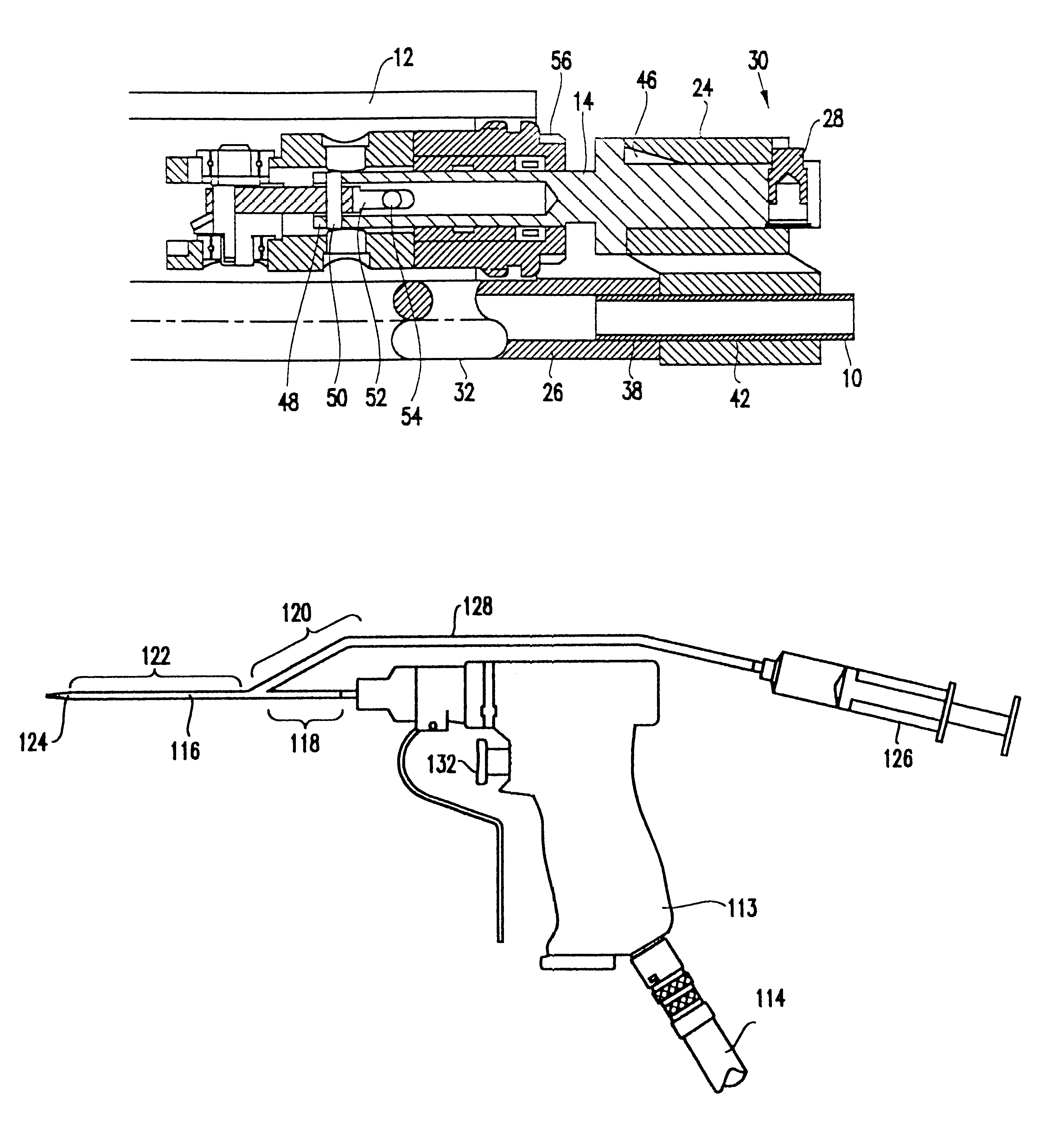
The vacuum hose can be securely connected to the handpiece housing by one or more slot members positioned on the housing. Hence, a surgeon can simply press-fit the hose into the slots on the hand piece, and then secure the hose end to a projection on the connector. Because the hose is made of an elastic material, such as polyvinylchloride, the hose can axially stretch and contract with each reciprocating movement of the cannula / connector combination without narrowing the passage in the hose to a point where vacuum pressure cannot be exerted, and without causing the hose to slip from the slot members. By using an optically clear hose material, the surgeon will be permitted to see when clogs from aspirated fat material occur, so that corrective measures can be taken.

Problems solved by technology

This technique requires significant effort on the part of the surgeon in terms of both the physical effort required to move the cannula back and forth, and the effort required to control the direction of movement of the cannula in order for fat tissue to be withdrawn only from specific areas of the patient's body.
The disadvantage of both these approaches is that they do not control the direction of liposuction, and can lead to withdrawing fat tissue unevenly, thus producing a lumpy surface upon completion of the surgery.
A disadvantage with each of these Swartz and Clark designs is that they tend to tear the tissue.
This can be problematic when working in confined spaces near blood vessels and the like.
However, the Cucin design is fairly clumsy and requires the cannula and reciprocating mechanism to move within a portion of the hand held base unit.
Overall, the Greco system is complex and subject to a variety of drive control problems, as well as high costs for various elements.
In addition, the Greco system is designed to provide cannula stroke lengths which are in excess of 1 cm, which is not ideal in a number of different circumstances.
The design in U.S. Pat. No. 5,348,535 is complex in that it requires multiple sleeves, and the reciprocating movement causes periodic changes in the aspiration aperture.

Method used


Image

  • Power assisted liposuction and lipoinjection equipment
  • Power assisted liposuction and lipoinjection equipment
  • Power assisted liposuction and lipoinjection equipment

Examples


Embodiment Construction

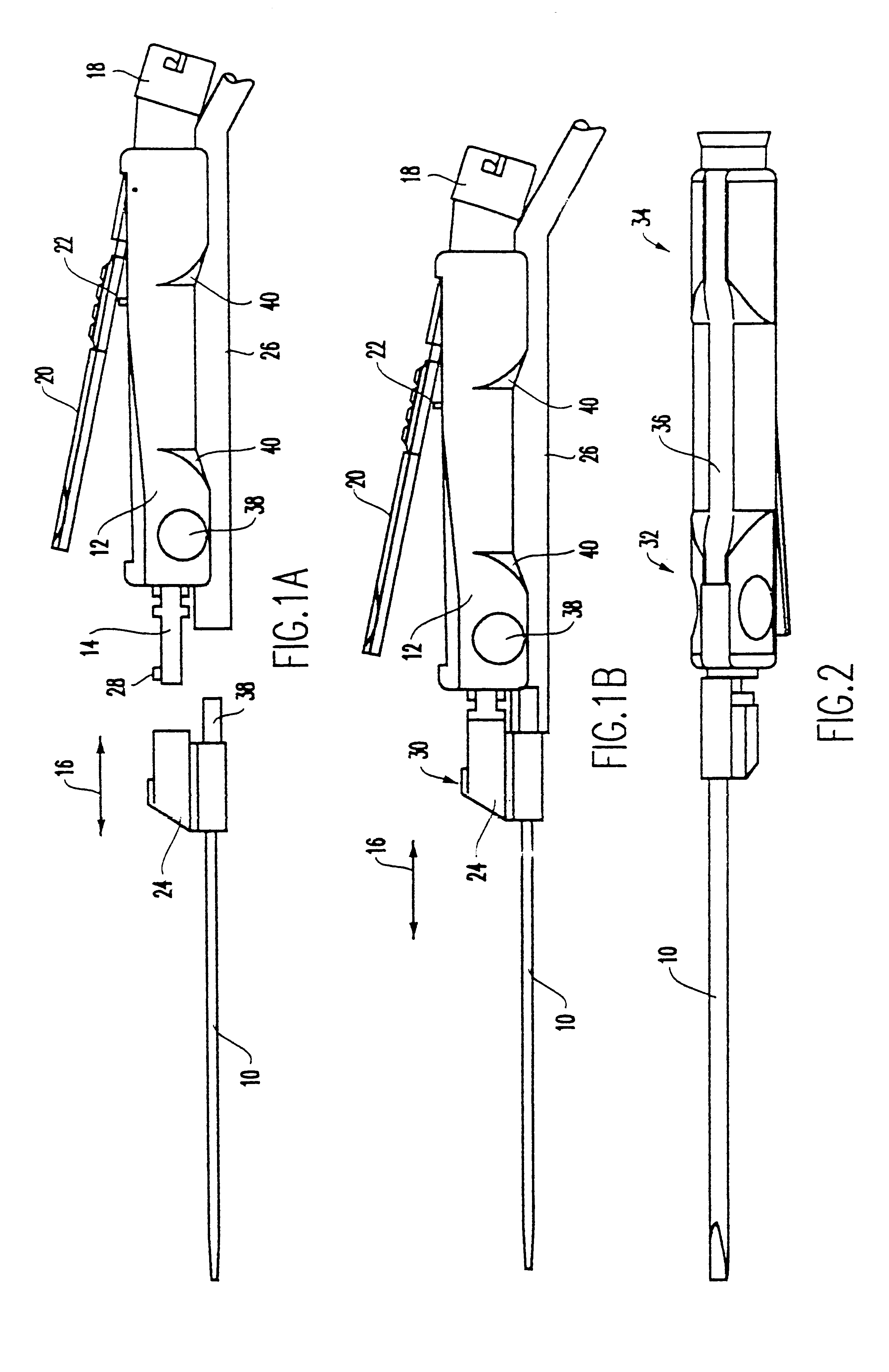
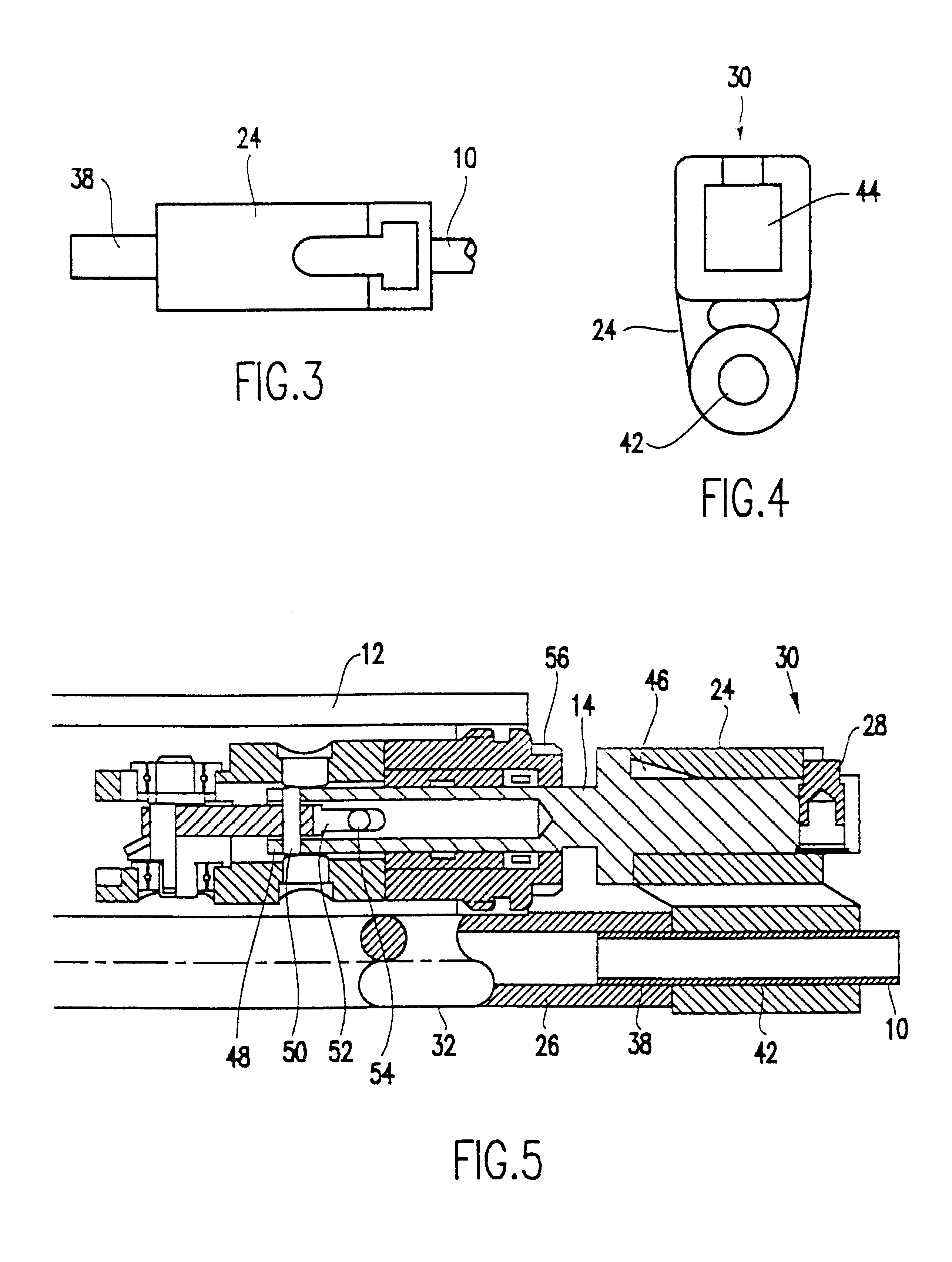
FIGS. 1a and 1b show the preferred embodiment of the power assisted liposuction / lipoinjection handpiece of the present invention. A cannula 10 is selectively connectable and disconnectable from a handle 12. The handle 12 includes a reciprocating member 14 which moves back and forth, as indicated by double headed arrow 16, in a reciprocating motion. In the preferred embodiment, the handle 12 includes a pneumatic drive assembly (not shown) and is connectable to a compressed air source by connector 18. An example of a suitable handle with internal pneumatic drive could be the MicroAire.RTM. 1400-100. However, it should be understood that any drive mechanism, including electrical, magnetic, etc., can be used to move the cannula 10 in a reciprocating motion 16.

The speed of reciprocation is preferably variable under the control of a lever 20 actuated button or switch 22, whereby complete depression of the lever 20 accelerates the reciprocation to its maximum speed, and partial depression ...


PUM


Abstract

A power assisted liposuction / lipoinjection handpiece includes a handle (12) which provides power to reciprocate a cannula (10) back and forth during surgery. The cannula (10) can be connected to the handle (12) by a connector (24) that is affixed to, integrally formed with, or selectively joinable to a reciprocating member (14). Benefits in sterilization, distribution and surgical use can be realized when the cannula (10) and connector (24) are joined together, such that the surgeon merely needs to remove the cannula (10) from the package and connect it to a reciprocating member of a powered handle (12). The handle (12) may be configured such that the reciprocating member (14) is selectively detachable; thereby, allowing the handle (12) to be used for additional surgical procedures such as sawing or drilling. A vacuum hose (26) is connected to the cannula (10) such that vacuum pressure can be exerted through the cannula (10) for aspirating severed fat tissue. Preferably, the connector (24) radially offsets the cannula (10) from the reciprocating member (14) to a position which is axially in alignment with the vacuum hose (26); thereby avoiding bend regions and enhancing suction.

Description

1. Field of the InventionThe invention is generally related to powered hand tools used in surgical operations and, more particularly, to hand tools used in liposuction and lipoinjection procedures.2. Background DescriptionLiposuction is a well known surgical procedure for surgically removing fat tissue from selected portions of a patient's body. Current practice is to make an incision and then insert a cannula in the space occupied by fat tissue. The cannula is then moved in such a manner as to mechanically break up the fat tissue. While moving the cannula, pieces of the fat tissue are aspirated from the space through the cannula by vacuum pressure from a syringe or pump. This technique requires significant effort on the part of the surgeon in terms of both the physical effort required to move the cannula back and forth, and the effort required to control the direction of movement of the cannula in order for fat tissue to be withdrawn only from specific areas of the patient's body. ...

Claims


Application Information

Patent Timeline
Patent Type & Authority Patents(United States)
IPC IPC(8): A61B17/32A61M1/00A61B17/00A61B17/22A61M37/00
CPCA61B17/32002A61M1/0086A61M2202/08A61M1/86
Inventor MOZSARY, PETER G.FARD, MIKEPASCALOFF, JOHN
Owner MICROAIRE SURGICAL INSTR
Learn More