Engine valve disabler

Inactive Publication Date: 2001-07-17
MOYER DAVID F
View PDF18 Cites 90 Cited by
  • Summary
  • Abstract
  • Description
  • Claims
  • Application Information

AI Technical Summary

Benefits of technology

Computer 37 exercises its cylinder disabling control by means of the disabler shown in cross section in FIG. 2. Disablers 22 and 25 are identical in form and operation. Stator 3 is formed of a soft magnetic material and shaped like a cylinder capped with a hollow rivet whose stem, having a rounded end is roughly one half the length of the cylinder. Sleeve bearing 2 is pressed within the center of stator 3 so as to guide pin 1

Problems solved by technology

This approach has had limited success in practice because the usual control activates or deactivates half the number of cylinders, and this abrupt change in output torque causes poor drivability.
Furthermore, the disabling mechanism is relatively slow acting so that more than one revolution of the crank

Method used


Image

  • Engine valve disabler
  • Engine valve disabler
  • Engine valve disabler

Examples


Embodiment Construction

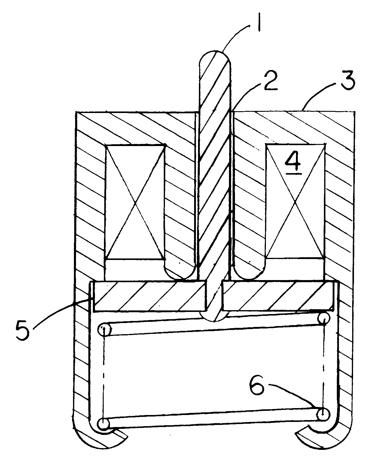
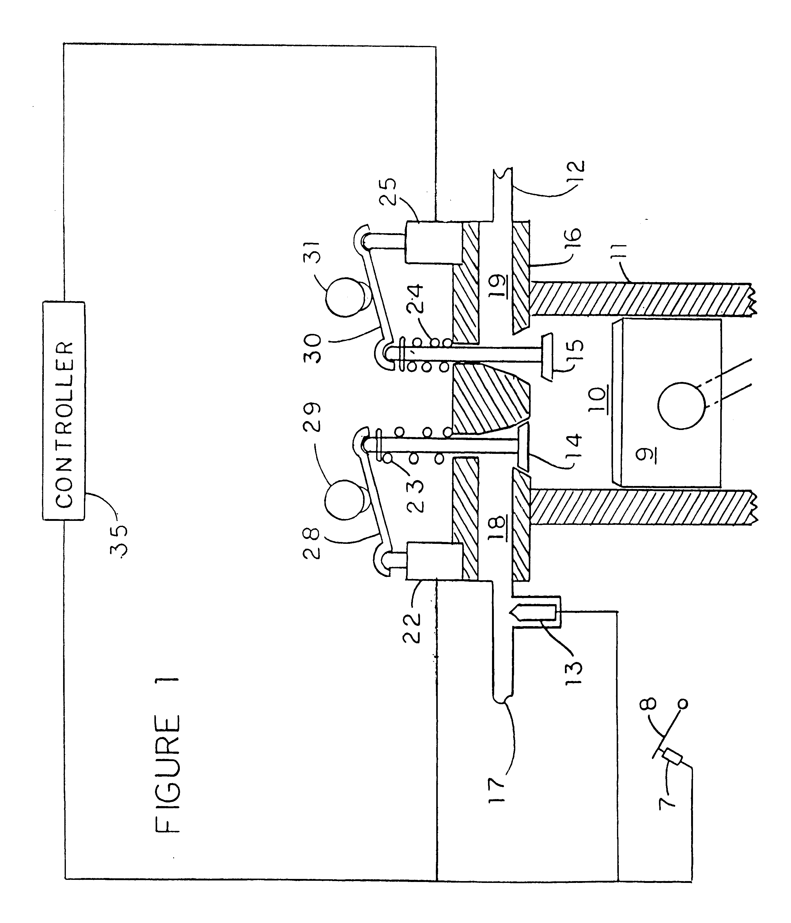
FIG. 1 shows a cross section of one cylinder 10 of a vehicle engine with engine block 11, which has a plurality of cylinders. A piston 9 is mounted for reciprocal motion within cylinder 10. A spark plug (not shown) ignites the fuel-air mixture in the usual fashion. Piston 9 is mechanically connected to a crankshaft (not shown) which transforms the reciprocal motion to rotary motion in the usual fashion. Also in the usual fashion, the crankshaft is connected to the wheels of the vehicle through a transmission and differential (not shown). Valve fulcrums 22 and 25 are used to provide engine valve control.

The inputs for controller 35 are an accelerator position sensor 7, and current engine system sensors (not shown). The outputs from controller 35 are an intake valve control 22, an exhaust valve control 25, fuel injector 13, and current engine controls (not shown).

During vehicle operation, when accelerator pedal 8 is depressed or released, controller 35 calculates the power required by...


PUM


Abstract

A method for improving efficiency and reducing emissions of an internal combustion engine. Variable displacement engine capabilities are achieved by disabling engine valves during load changes and constant load operations. Active cylinders may be operated at minimum BSFC by intermittently disabling other cylinders to provide the desired net torque. Disabling is begun by early closing of the intake valve to provide a vacuum at BDC which will result in no net gas flow across the piston rings, and minimum loss of compression energy in the disabled cylinder; this saving in engine friction losses is significant with multiple disablements.

Description

CROSS REFERENCEThis application is an improvement of the valve disabler described in my U.S. Pat. No. 5,832,885 issued Nov. 10, 1998. It is incorporated herein by reference.1. Field of the InventionThe present invention relates to the field of internal combustion engines; more particularly to a method of controlling the engine intake and exhaust valves so as to produce a more efficient combustion process within the cylinder.2. Background of the InventionThis invention describes a method for increasing the efficiency and reducing the undesirable emissions of an internal combustion engine. While the general principles and teachings disclosed are applicable to all combustion engines, the invention is hereinafter described in detail in connection with its application to a reciprocating, fuel injected, spark ignited, multi-cylinder engine.As used herein, the term "engine" refers to a device which converts heat energy, released by the combustion of a fuel, into mechanical energy in a rota...

Claims


Application Information

Patent Timeline
IPC IPC(8): F01L13/00F01L9/04F01L1/08F01L9/20
CPCF01L1/08F01L9/04F01L13/0005F01L13/0015Y10T477/83F01L2009/0469F01L2103/01F01L2800/13F01L2303/01F01L2009/2169F01L9/20
Inventor MOYER, DAVID F.
Owner MOYER DAVID F
Why Eureka
Try Eureka