Use of static mixing element in connection with flow of gas and liquids through a production tubing

a technology of static mixing and flow pipe, which is applied in the direction of mechanical equipment, fluid removal, non-positive displacement pumps, etc., can solve the problems of increasing ineffective lifting contribution of static mixing elements

Inactive Publication Date: 2001-07-17
MAGNUS ARNE JOHANNES
View PDF13 Cites 14 Cited by
  • Summary
  • Abstract
  • Description
  • Claims
  • Application Information

AI Technical Summary

Problems solved by technology

Without such mixing elements the few gas bubbles which appear in the production tubing string, will only be greater and greater the further up they rise, which is to the fact that they become more and more ineffective as regards their lifting contribution.

Method used


Image

  • Use of static mixing element in connection with flow of gas and liquids through a production tubing
  • Use of static mixing element in connection with flow of gas and liquids through a production tubing
  • Use of static mixing element in connection with flow of gas and liquids through a production tubing

Examples


Embodiment Construction

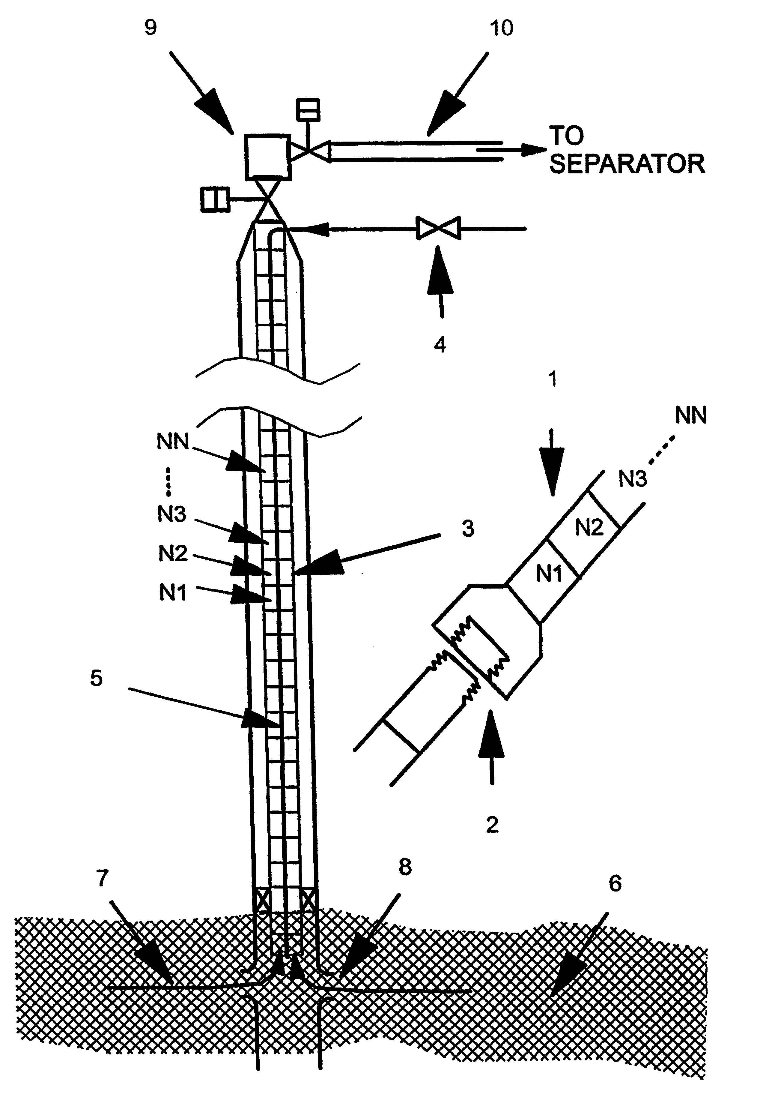
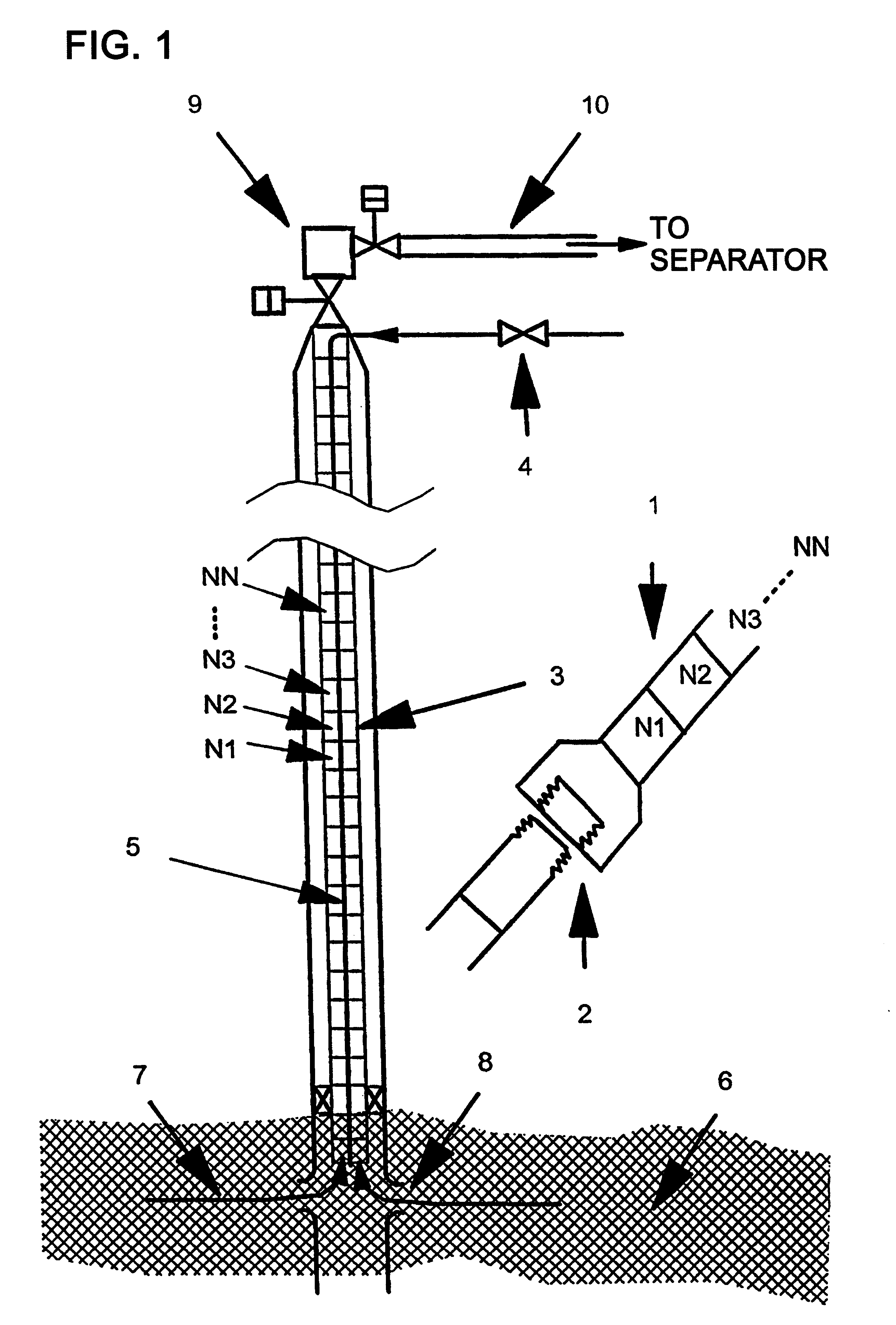
The invention can be used in a petroleum well with a production tubing string as illustrated in the attached FIG. 1.

The object of the invention is to stimulate petroleum wells of the type which has terminated--or almost terminated the production, by creating an optimum gas in liquid distribution and an optimum profile of the average gas / liquid density along the extent of the production tubing string. This in order to reduce the pressure head resistance at the bottom of the string as regards the flow of gas / liquid out of the reservoir.

The type of flow patterns which are found in typical production tubings in petroleum wells, is dependent upon gas / oil conditions and the pressure in the reservoir. The invention can be utilized in petroleum wells wherein the liquid portion is decreasing or terminates its flow by low reservoir head. By low head in the reservoir and a great contribution of liquid in the flow from the reservoir to the production tubing, it will be possible that the liquid ...


PUM


Abstract

The present invention relates to a method and a device in connection with a method for transport or flow of gas and liquid in a pipe, by which method there is in the overall or part of the pipe mounted static mixing elements for achieving favorable flows in the pipe, and for the purpose of being able to stimulate petroleum wells which have terminated production or almost terminated production due to high pressure head resistance, it is according to the invention suggested that the pipe which is used, is a production tubing or production string extending substantially vertically from a production reservoir having a low pressure, and that the mixing elements residing in the tubing is arranged in such a manner that the gas bubbles in the oil are distributed optimally as carriers in the oil, for thereby reducing and evening out the pressure head resistance in the tubing.

Description

The following invention relates to a use in connection with transport or flow through a production tubing string in a petroleum well of gas and liquid from a petroleum reservoir with low pressure, where the flowing fluid comprises a substantial liquid part and a less gas contribution, which gas mostly flows or bubbles past or through the liquid in the production tubing.In other words, it can be said that the present invention relates mainly to the type of petroleum wells which may be termed an oil producer, such oil producer producing mainly oil and some gas. This is different from petroleum wells (reservoirs) which are termed gas producers, which gas producers often also produce some liquid, for example in the form of condensate and water. By such a liquid production (in a gas well) and low pressure in the reservoir, such a well could, however, gradually "drown", and the need for gas lift may be required. Thus, the present invention also relates to gas lift for gas wells.Most petro...

Claims


Application Information

Patent Timeline
Patent Type & Authority Patents(United States)
IPC IPC(8): E21B43/12F04F1/00F04F1/08
CPCF04F1/08E21B43/121
Inventor MAGNUS, ARNE JOHANNES
Owner MAGNUS ARNE JOHANNES
Why Eureka
Try Eureka