Flame cover

a flame cover and flame technology, applied in the field of mechanical candle holders, can solve the problem of unadjustable protection of the operation of the lighted candle in an open spa

Inactive Publication Date: 2001-07-17
BENTLEY MEGAN +1
View PDF19 Cites 22 Cited by
  • Summary
  • Abstract
  • Description
  • Claims
  • Application Information

AI Technical Summary

Problems solved by technology

In many areas, governmental fire code regulations prohibit the operation of a lighted candle in an open space without adequate protection.

Method used


Image

  • Flame cover
  • Flame cover
  • Flame cover

Examples


Embodiment Construction

)

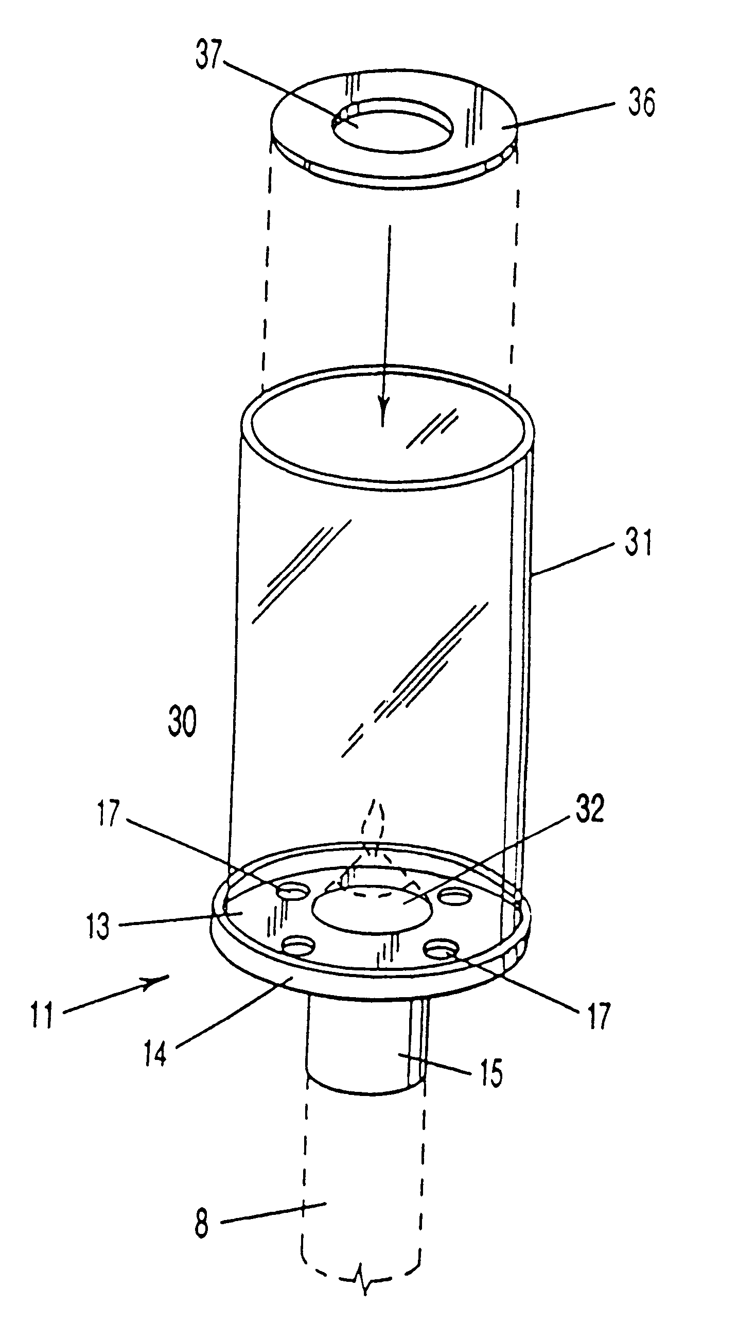
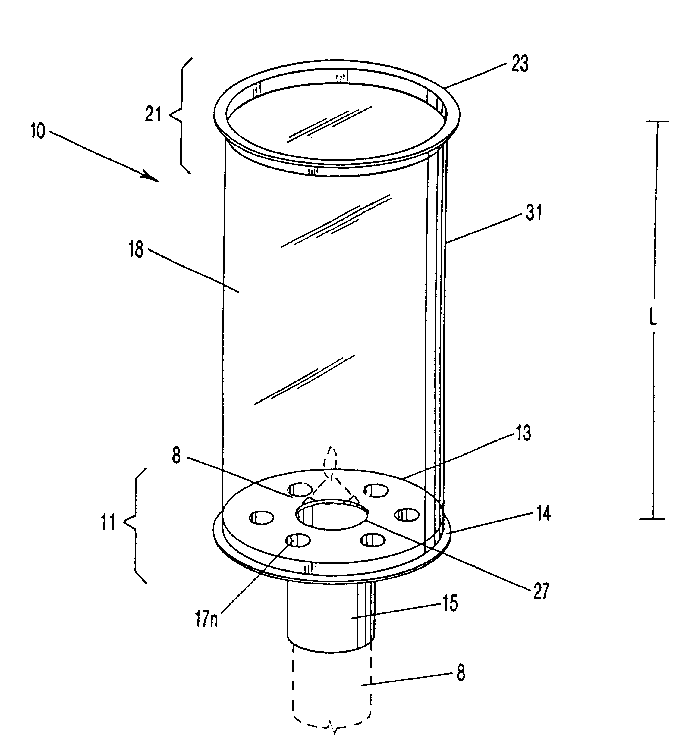
The present invention, a flame cover, is illustrated in FIG. 1. A seen in FIG. 1, the present invention is a flame cover 10 for a mechanical candle holder 8 (such as a Chace Candle holder) comprising three components: a base 11, an annulus 21 (optional) and a shell 31 therebetween.

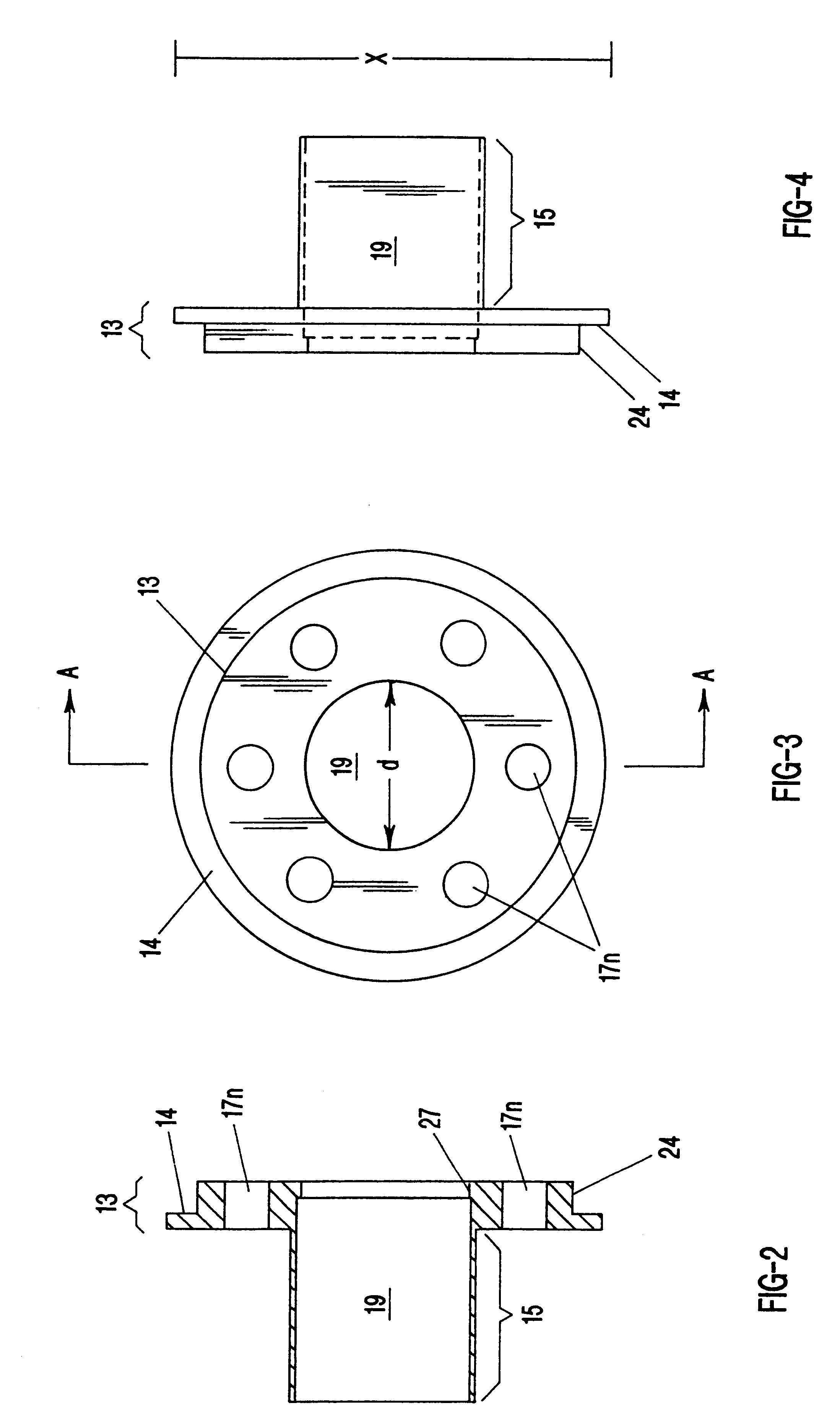
As illustrated in FIGS. 1-5, base 11 includes a rim 13 coupled to a hollow elongated conduit 15 depending downward from the rim. The upper end of the tube of the mechanical candle holder 8 (such as a Chace Candle holder) is insertable into conduit 15 so that the flame cover 10 can be rested upon the upper end or taper of the tube 8 (as shown in dashed lines) with the tube removably but firmly engaged with the conduit 15 of the base 11. The rim 13 has a lip 27 and center hole defined therein of diameter corresponding generally to the diameter of the channel 19, so that when the flame cover 10 is in use, the upper end of the tube 8 of the mechanical candle holder is disposed through the conduit 15 and exten...


PUM


Abstract

A flame cover device for use with mechanical candle holders, especially for use with candle holders in which the candle is spring-driven to the top of a tube as the candle is consumed. The apparatus may be removably disposed upon the top portion of the tube of the mechanical candle holder, where it remains motionless while the candle is burned by combustion, yet provides protection from and to the burning flame. A base of the device is engaged with the tube of the mechanical candle holder, with vents in the base providing adequate ventilation to the flame. A transparent shell extends up from the base to provide flame protection. A ring damper is provided for covering the vents in the base to assist the flame in windy conditions.

Description

1. Field of the Invention (Technical Field)The present invention relates to mechanical candle holders, and more particularly, to a removable flame cover for a mechanical candle holder which decreases or prevents the risk of injury or damage from the candle's open flame while simultaneously allowing the mechanical candle to be used in the presence of air currents without extinguishing the flame.2. Background ArtA mechanical candle holder maintains a candle upon a surface, such as a table. The candle is held by a base, and disposed within a vertically oriented tube, and includes a spring or other mechanical means for urging progressively the candle to the upper portion of the tube, so that the entire candle is ultimately consumed over the course of its burning, but the flame is maintained at a fixed position above the supporting surface. Such a device is disclosed, for example, in U.S. Pat. No, 2,469,163 to Chace Gilmore. Devices manufactured after the teachings of this seminal patent...

Claims


Application Information

Patent Timeline
Patent Type & Authority Patents(United States)
IPC IPC(8): F21V37/00F21V35/00
CPCF21V25/00F21V37/0075F21V35/00
Inventor BUTLER, WILLIAM ROBERTSON
Owner BENTLEY MEGAN
Why Eureka
Try Eureka