Combination read/write thin film magnetic head and its manufacturing method

a technology of read/write and magnetic heads, applied in the functional testing of recording heads, recording information storage, instruments, etc., can solve the problems of inability to detect high precision, significant affecting the pitch of high density recording, and tracking servo errors

Inactive Publication Date: 2001-07-17
TDK CORPARATION
View PDF24 Cites 14 Cited by
  • Summary
  • Abstract
  • Description
  • Claims
  • Application Information

AI Technical Summary

Problems solved by technology

The write fringing inhibits high precision detection of the track position in the written recording medium and results in tracking servo errors.
In particular, the write fringing significantly affects high density recording with a narrow track pitch.
A finer track pitch for high density recording will cause some detecting errors due to the write fringing shown in FIG. 16B, and thus the improvement shown in the drawing will be insufficient.
Such a chlorine-based gas is, however, highly corrosive to the magnetic materials of the upper- and lower-core layers.

Method used


Image

  • Combination read/write thin film magnetic head and its manufacturing method
  • Combination read/write thin film magnetic head and its manufacturing method
  • Combination read/write thin film magnetic head and its manufacturing method

Examples


third embodiment

(3) Combination read / write thin film magnetic heads C1 and C2 in accordance with the present invention shown in FIG. 7, in which the tilting angles of the slanted surfaces 1b formed on the lower-core layer 1 are 2 degrees and 4 degrees, respectively.

second embodiment

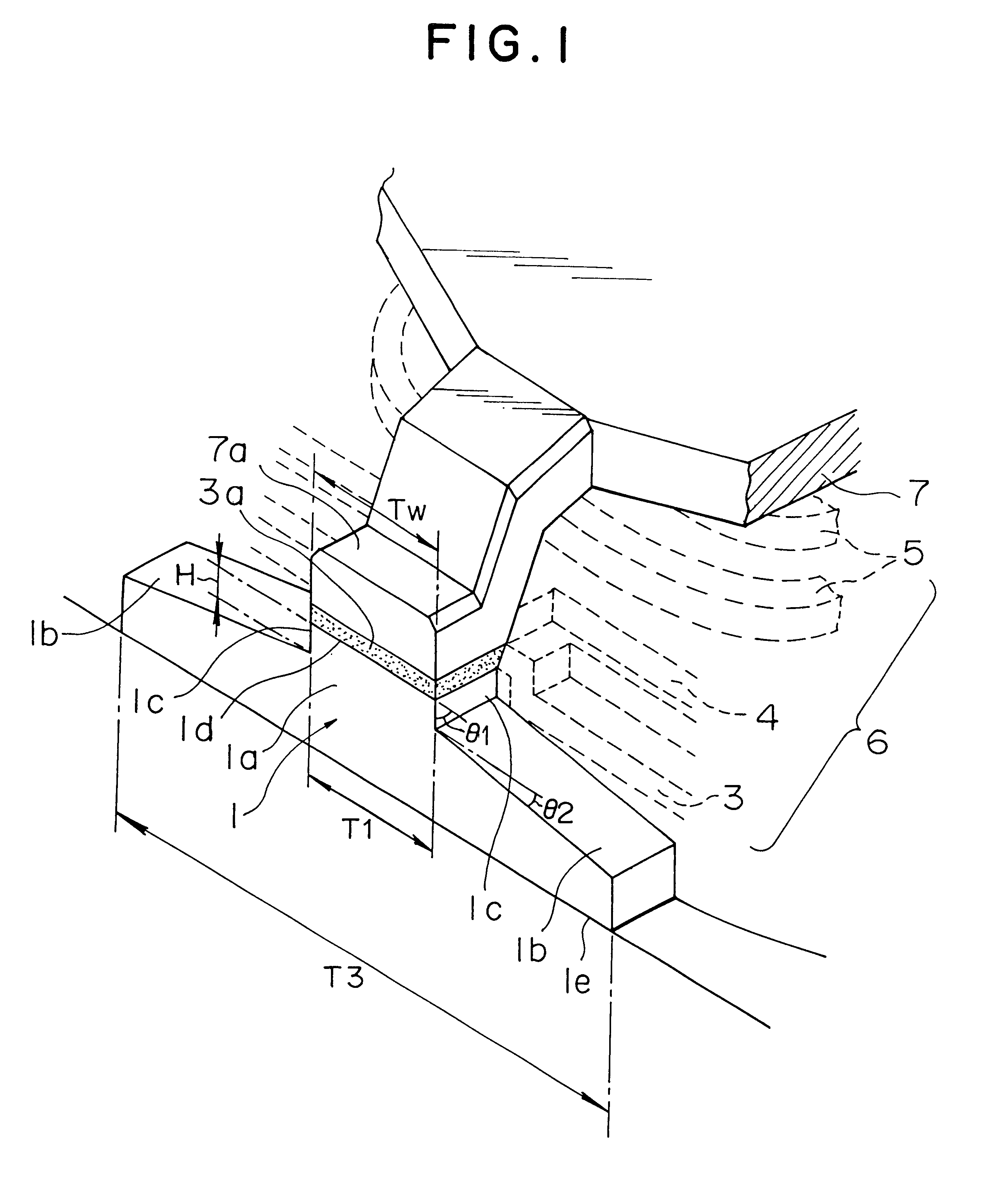
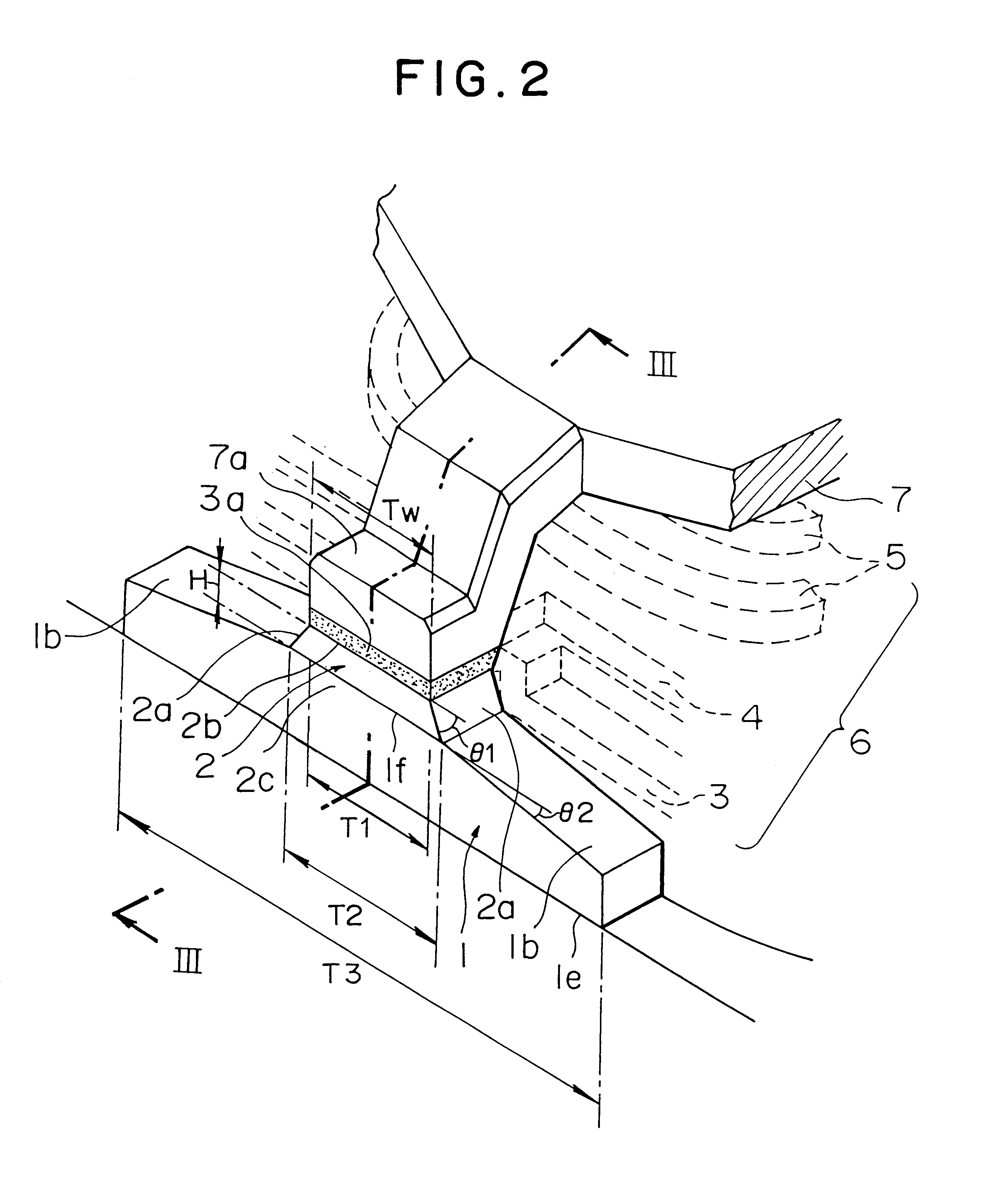
(4) Combination read / write thin film magnetic heads D1, D2 and D3 in accordance with the present invention shown in FIG. 2, in which the height H of the prominence 2 formed on the lower-core layer 1 is 0.5 .mu.m for all the heads, the tilting angles .theta.1 of the slanted surfaces 2a formed on the prominence 2 are 30 degrees for D1, 45 degrees for D2 and D3, and the tilting angles .theta.2 of the slanted surfaces 1b formed on the lower-core layer 1 are 2 degrees for D1 and D2 and 5 degrees for D3.

first embodiment

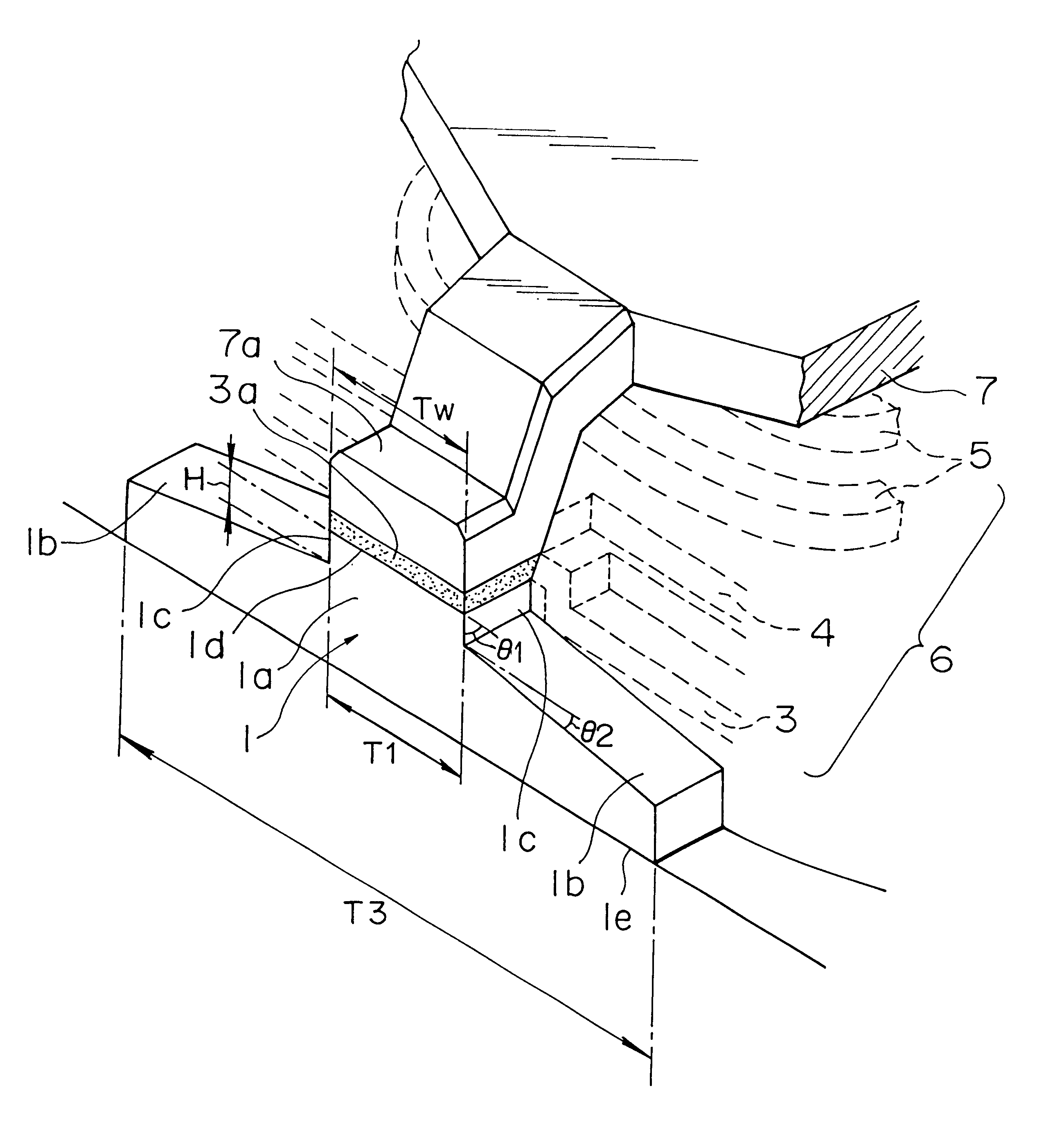
(5) Combination read / write thin film magnetic heads E1, E2 and E3 in accordance with the present invention shown in FIG. 1, in which the heights H of the prominence 1a formed on the lower-core layer 1 are 0.2 .mu.m for E1, 0.4 .mu.m for E2 and E3 and, and the tilting angles .theta.2 of the slanted surfaces 1b formed on the lower-core layer 1 are 2 degrees for E1 and E2 and 5 degrees for E3.

All the combination read / write thin film magnetic heads had the same thickness of the gap layer of 0.3 .mu.m.

Signals were recorded with each of the combination read / write thin film magnetic heads the on a recording magnetic medium and the width To of the signals was determined with a magnetic force microscope (MFM).

The width Tw of the front end of the upper-core layer of each combination read / write thin film magnetic head was determined with a scanning electron microscope.

The write fringing length of each head was calculated from the difference between the width To of the recorded signals and the ...


PUM

PropertyMeasurementUnit
angleaaaaaaaaaa
angleaaaaaaaaaa
angleaaaaaaaaaa

Abstract

A method for manufacturing a combination read / write thin film magnetic head comprising the steps of: forming a nonmagnetic material layer on a lower-core layer and forming an upper-core layer having a width smaller than that of the lower-core layer on the nonmagnetic material layer; leaving the section of said nonmagnetic material layer sandwiched between the lower-core layer and the upper-core layer as a gap layer and removing the nonmagnetic material layer not covered by the upper-core layer, said step for removing said nonmagnetic material being performed by an anisotropic plasma etching process using a CF4 based gas; trimming both ends of the facing surfaces, to be in contact with said gap layer, of the lower-core layer so as to equalize the width of the facing surface with the width of the upper-core layer, and forming a prominence above the lower-core layer facing the upper-core layer through the gap layer; and forming grades on both upper surfaces of the lower-core layer extending from the base ends of the prominence in the direction away from the upper-core layer.

Description

1. Field of the InventionThe present invention relates to combination read / write thin film magnetic heads used in floating-type magnetic heads and the like. In particular, the present invention relates to a combination read / write thin film magnetic head and a method for making the same, in which the track width of a magnetic gap of an inductive thin film magnetic head is highly precisely formed in order to reduce occurrence of write fringing.2. Description of the Related ArtFIG. 14 is a longitudinal sectional-view of a conventional combination read / write thin film magnetic head, and FIG. 15 is a section facing a recording medium of the magnetic head shown in FIG. 14 and a fragmentary front view along arrow XV in FIG. 14. The magnetic head shown in FIGS. 14 and 15 is an inductive magnetic head which writes signals on a recording medium such as a hard disk. The inductive magnetic head is superposed with a reading head which uses the magnetoresistance effect at the trailing edge of the...

Claims


Application Information

Patent Timeline
Patent Type & Authority Patents(United States)
IPC IPC(8): G11B5/39G11B5/31G11B5/455
CPCG11B5/3967G11B5/3116G11B5/3163Y10T29/49046G11B5/455G11B5/3166G11B5/127
Inventor SATO, KIYOSHIISHIBASHI, NAOHIRO
Owner TDK CORPARATION
Why Eureka
Try Eureka