Mouse emulation with a passive pen

a passive pen and mouse technology, applied in the field of mouse emulation with a passive pen, can solve the problems of limited application programs for such pen-based systems, less popularity of such pen-based computer systems,

Inactive Publication Date: 2001-07-17
NEC CORP
View PDF78 Cites 129 Cited by
  • Summary
  • Abstract
  • Description
  • Claims
  • Application Information

AI Technical Summary

Problems solved by technology

Unfortunately, the popularity of such pen-based computer systems is a lot less than was expected by the industry.
As such, application programs for such pen-based systems are limited.

Method used


Image

  • Mouse emulation with a passive pen
  • Mouse emulation with a passive pen
  • Mouse emulation with a passive pen

Examples


Embodiment Construction

of the Schematic Diagrams

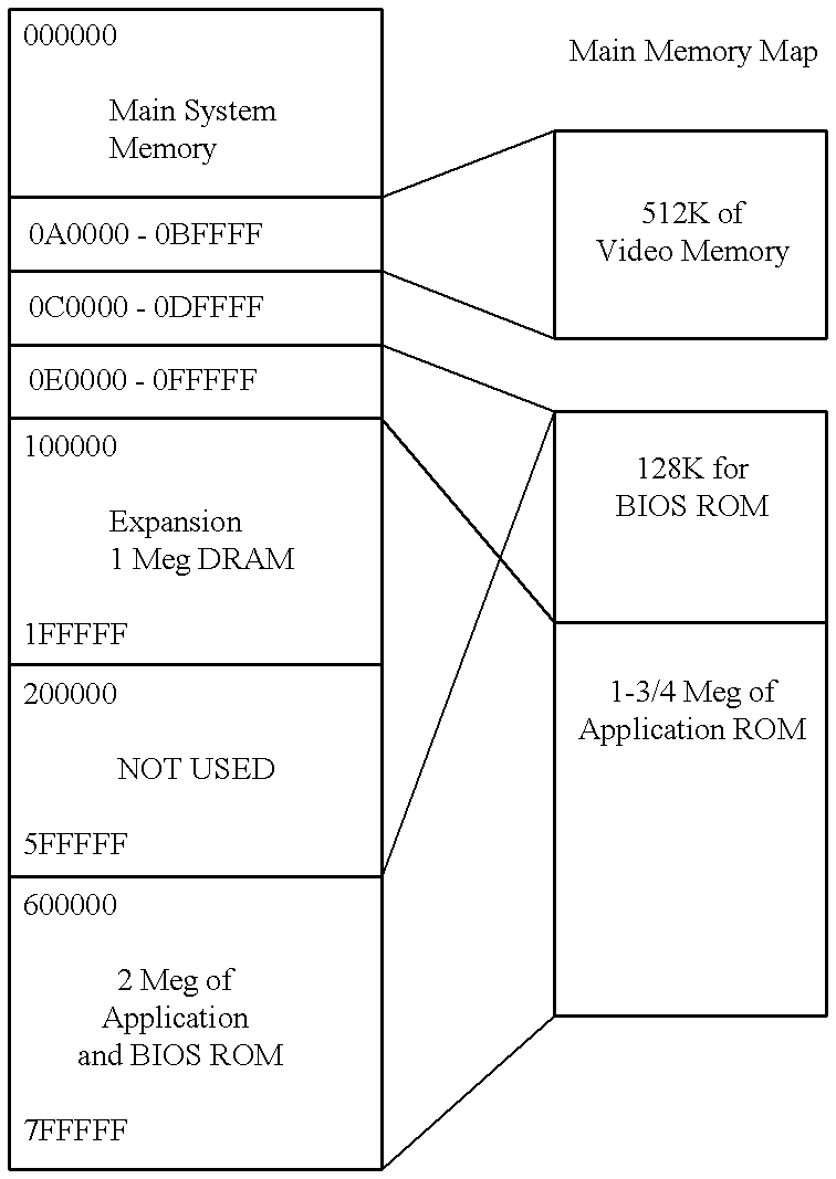
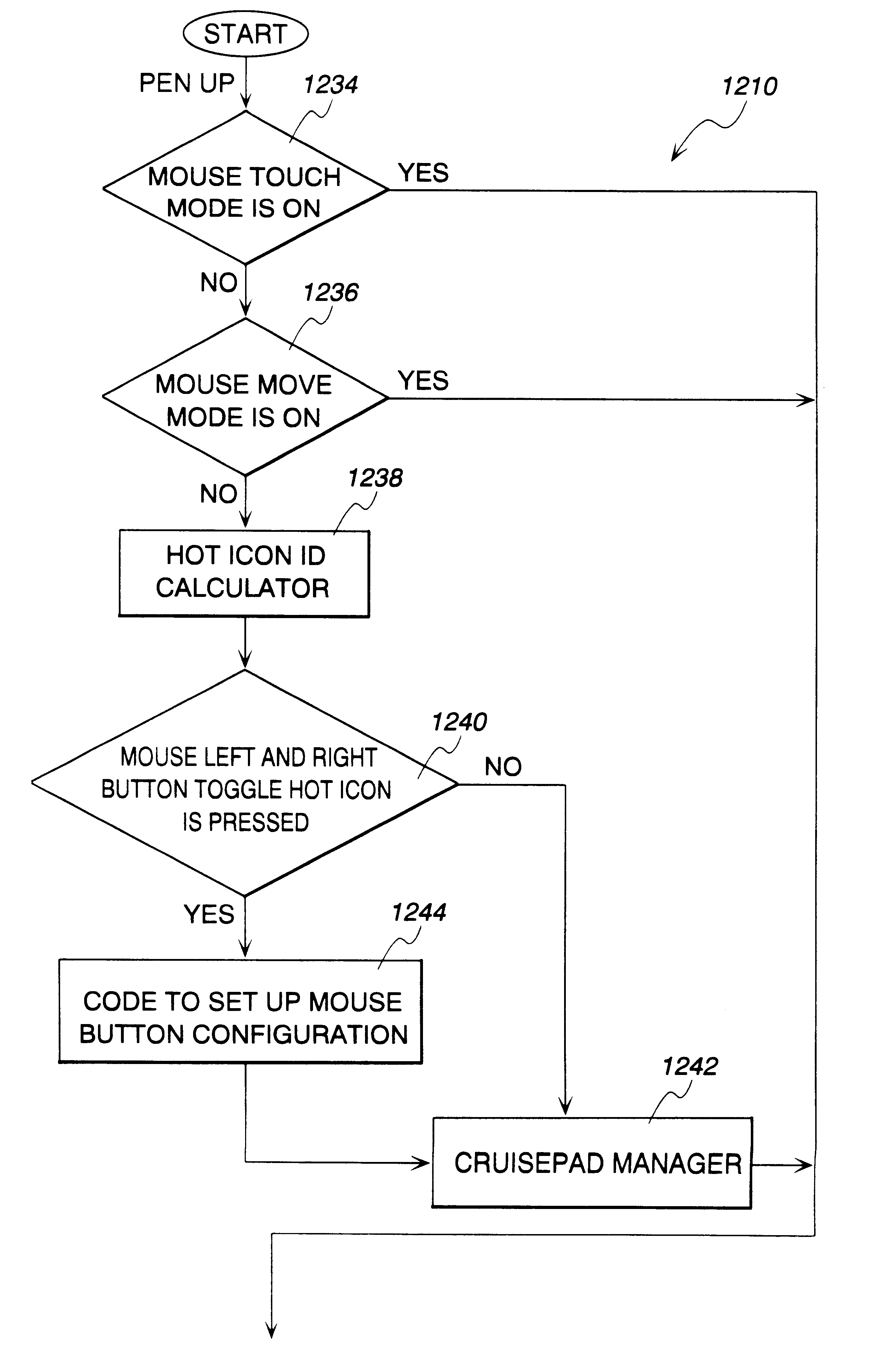
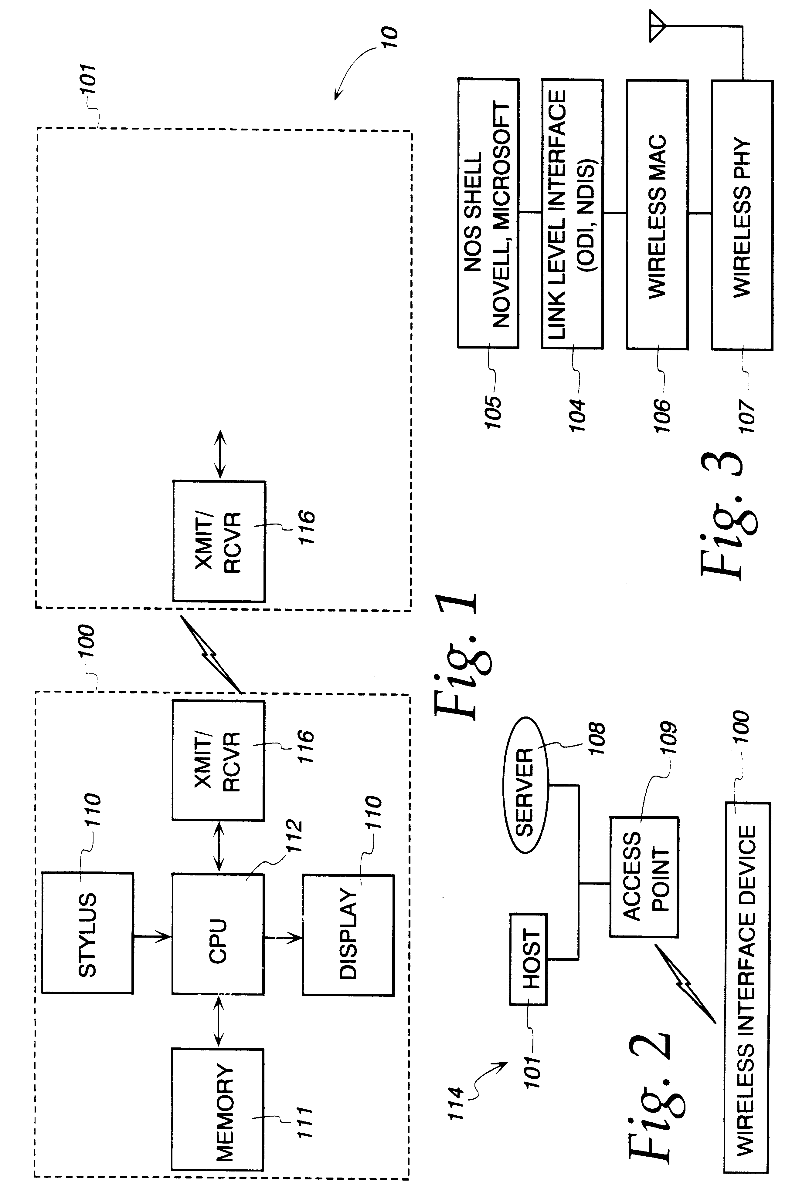
One embodiment of the invention is illustrated in the schematic drawings, FIGS. 11-30. Referring to FIG. 11, the system may include a CPU 112, such as an AMD Model No. AM386DXLV microprocessor. The CPU 112 includes a 32-bit data bus D[0 . . . 31] as well as a 32-bit address bus A[2 . . . 31]. Both the data bus D[0 . . . 31] as well as the address bus A[2 . . . 31] are connected to the processor bus 150 (FIG. 4), for example, an AT bus. As will be discussed in more detail below, the system controller 129 (FIG. 4) performs various functions including management of the processor bus 150. In order to conserve power, a 3-volt microprocessor may be used for the CPU 112. As such, a 3-volt supply 3V CPU is applied to the power supply VCC pins on the CPU 112. The 3-volt supply 3V_CPU is available from a DC-to-DC converter 300 (FIG. 26) by way of a ferrite bead inductor 302. In particular, the DC-to-DC converter 300 includes a 3-volt output, 3V_CORE. This output, 3V_C...


PUM


Abstract

A pen-based portable personal computer can emulate the functions of a standard two-button mouse. In particular the system can emulate standard movement and clicking of a mouse buttons as well as emulate both left and right mouse buttons of a two-button mouse. In order to be compatible with various application programs, the system can also emulate the double clicking of the mouse button. By providing a pen-based computer system which can emulate the functions of a standard two-button mouse, the system is compatible with various application programs available on the market

Description

1. Field of the InventionThe present invention relates to a pen-based portable personal computer system and more particularly to a system for emulating the functions of, for example, a two-button mouse, utilizing a passive stylus as an input device.2. Description of the Prior ArtPen-based portable personal computer systems are generally known in the art. Such systems typically include a digitizer panel and utilize a stylus as an input device. Both active and oassive stylus' are known. In such pen-based personal computer systems, the path of the stylus is tracked relative to the digitizer panel to maintain the pen paradigm and to provide visual feedback to the user. Such pen-based portable personal computer systems are known to use Microsoft Windows for Pen Computing Systems ("Pen Windows"). When the system is utilizing pen Windows, the pen driver can typically deliver stylus tip locations every 5-10 milliseconds ("100-200 times per second") to achieve a resolution of about 200 dots ...

Claims


Application Information

Patent Timeline
Patent Type & Authority Patents(United States)
IPC IPC(8): G06F1/00G06F21/00G06F3/033H04L29/06H04L29/08G06F3/048
CPCG06F1/3262G06F3/0488G06F3/04883G06F3/04886G06F21/83H04L67/1095H04L67/36H04L67/34H04L69/04H04L67/04H04L67/06G06F2211/1097H04L69/22H04L67/75
Inventor BI, DEPENGCOHEN, GARY STEVENCORTOPASSI, MICHAELGEORGE, JOSE T.GLADWIN, S. CHRISTOPHERHSIUNG, HARRYLIM, PENGPARHAM, JOHN ALLANSOUCY, ALAN JOSEPHVOEGELI, DERICK W.WILSON, JAMES Y.
Owner NEC CORP
Why Eureka
Try Eureka