Telephone having an internally lit display

a technology of internal lighting and telephone, which is applied in the field of telephones, can solve problems such as poor appearance quality

Inactive Publication Date: 2001-07-17
FUJITSU LTD
View PDF5 Cites 25 Cited by
  • Summary
  • Abstract
  • Description
  • Claims
  • Application Information

AI Technical Summary

Problems solved by technology

Thus, unevenness in brightness occurs in each key top and thus an appearance quality is poor.
Further, the openings of the sheet luminescent member allow the projections of key tops to pass therethrough, and therefore, provision of the sheet luminescent member does not degrade an easy operation condition of the key tops.

Method used


Image

  • Telephone having an internally lit display
  • Telephone having an internally lit display
  • Telephone having an internally lit display

Examples


first embodiment

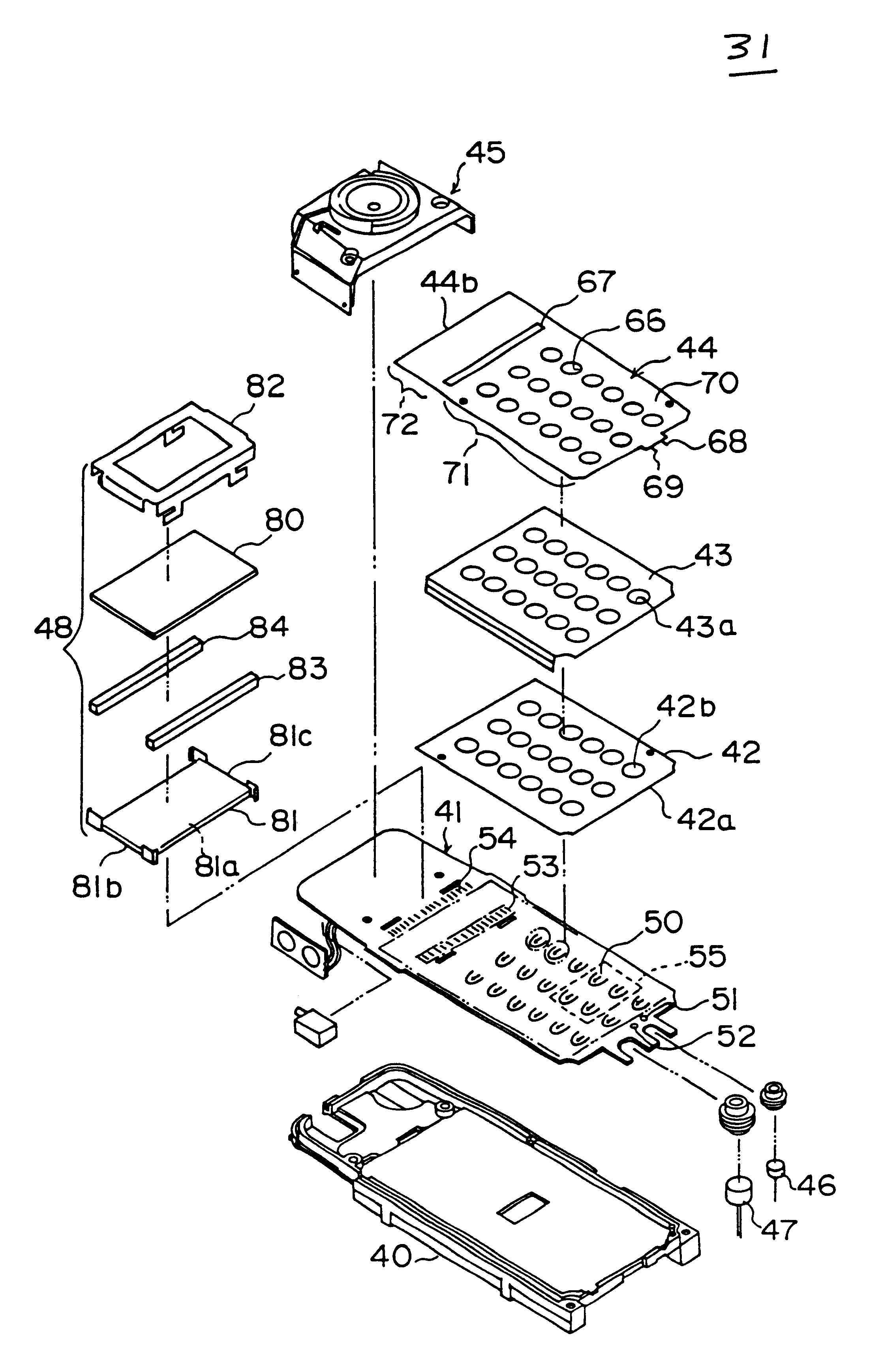
In the first embodiment, the sheet luminescent member 44 includes both the keypad facing portion 71 facing the keypad 32 and the liquid-crystal-display-assembly facing portion 72 facing the liquid crystal display assembly 48. However, a structure is also possible in which the sheet luminescent member 44 includes only the keypad facing portion 71 facing the keypad 32. Similarly, a structure is also possible in which the sheet luminescent member 44 includes only the liquid-crystal-display-assembly facing portion 72 facing the liquid crystal display assembly 48.

Further, instead of using the integral keypad 32, it is also possible to use separate key tops assembled individually.

second embodiment

the present invention will now be described. For the second embodiment, a detailed description will be omitted because the second embodiment has a structure similar to that of the first embodiment described above.

FIG. 12 shows an exploded, perspective view of a telephone body assembly 31A of a portable telephone in the second embodiment of the present invention. The telephone body assembly 31A has a structure the same as that of the telephone body assembly 31 in the portable telephone in the first embodiment shown in FIG. 5, except for a structure of the sheet luminescent member.

A sheet luminescent member 44A of the telephone body assembly 31A in the second embodiment is obtained as a result of modifying the sheet luminescent member 44 in the telephone body assembly 31 in the first embodiment, as will now be described. A portion between the slender opening 67 and the side 44b is removed from the sheet luminescent member 44. Thereby, a rectangular cut-out 44Aa is provided having a si...

third embodiment

FIG. 14 shows an exploded, perspective view of a telephone body assembly 31B of a portable telephone in the present invention. The telephone body assembly 31B has a structure the same as that of the telephone body assembly 31 shown in FIG. 5, except for the sheet luminescent member.

FIG. 15 shows a perspective view of a part of a sheet luminescent member 44B in the third embodiment, the part resulting from cutting the sheet luminescent member 44B along a line passing through the centers of openings 66, and the view including a view of the cut surface of the part. As shown in FIG. 15, the sheet luminescent member 44B includes the rear insulation layer 60, rear electrode layer 61, dielectric layer 62, phosphor layer 63 and transparent front electrode layer 64, which layers are stacked. Further, a metallic sheet 100 is stacked on the rear surface of the rear insulation layer 60. The metallic sheet 100 has an electric shielding function. The sheet luminescent member 44B has the electric ...


PUM


Abstract

A telephone including a case; an operation part, located at a front of the case, having a light transmission property and a plurality of key tops arranged on a front surface thereof; a circuit substrate, provided inside the case and having a sheet-luminescent-member driving circuit; and a sheet luminescent member, provided at a rear of the operation part, between the circuit substrate and the case. Light emitted by the sheet luminescent member fully illuminates each key top from the rear surface thereof.

Description

1. Field of the InventionThe present invention relates to a telephone and, in particular, to a portable telephone.In consideration of use at night, a portable telephone has a device for lighting each key of a keypad from the inside of the portable telephone. In order to improve an appearance quality of the portable telephone, it is preferable that the lighting device lights each key uniformly.2. Description of the Related ArtFIG. 1 shows an example of a telephone in the related art. The portable telephone 10 has a structure in which a telephone body assembly 11 and a keypad 12 are contained in a case assembly 15 which consists of a combination of a rear case assembly 13 and a front case assembly 14.The telephone body assembly 11 has a plurality of LEDs (Light-Emitting Diodes) 17, each between adjacent key contacts 16. When it is used at night, a button for lighting is pressed, the LEDs 17 emit light, and the light 18 from the LEDs 17 propagates and diffuses as indicated by arrows sh...

Claims


Application Information

Patent Timeline
Patent Type & Authority Patents(United States)
IPC IPC(8): H04M1/23H04M1/22
CPCH04M1/23H04M1/22H01H2205/026H01H2215/036H01H2219/018H01H2231/022H01H2239/004H01H2219/046
Inventor KUBO, HIROSHIKOBAYASHI, HIDEKATSUTOMURA, MASASHI
Owner FUJITSU LTD
Why Eureka
Try Eureka